


Magnum 6K25 Managed Fiber Switch Installation and User Guide (04/06)
26
www GarrettCom com
..
D D
C
C
B B A A
D D C
C
B B A A
D D
C
C
B B A A
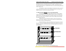
Standard Flush
Mount Bracket
Mid-Range Mount or
5” Set-Back Bracket
Rear Mount Bracket
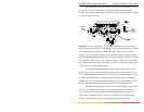
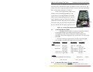
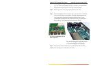
The bracket mounting holes in the sides of the Magnum 6K25 permits it to be
mounted in various ways. The same holes fit all three types (19”, ETSI, 23”) of brackets.
The mounting for the 23” is illustrated in Figure 3.3.1 below. The brackets may be
attached flush with the front, or attached in the center for a set-back mounting which may
reduce cabling torque.
The optional 23” brackets and the ETSI (21”) brackets each come as a pair in a
package, along with the necessary screws for attaching the brackets to the sides of the
Magnum Switch unit. They must be ordered as line items.
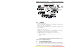
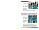
3.3.2 Rack-mounting, Reverse version of the Magnum 6K25s
The optional Reverse Magnum 6K25 Model has all of the cabling (Ethernet
cabling, power cabling and console port cabling) connectors in the rear, and the status
LEDs in the front. The status LEDs that are co-incident with the ports are still present
there, and a second or dual set of LEDs are used for status visibility in the front of the
unit, showing the same data.
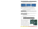
There are three options of brackets available to mount in the standard 19”
frame or the 23” frame or ETSI (21”) frame. The 19” brackets are included with each
unit, the other two may be purchased if desired.
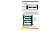
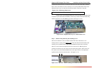
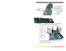
With each bracket type, there are three different mounting options is shown in
Fig. 3.3.2. The case of the Magnum 6K25 has mounting holes prepared for each of the
mounting arrangements. Users may choose the mounting arrangement most suitable for
their installation.
Fig 3.3.2 Reverse Magnum 6K25 units, rack-mounted in a frame