


F-36 PRO Laminator Operation Manual
Operation
© GBC Pro-Tech 1999 January
3-7
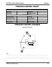
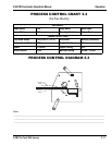
1. Adjust the machine settings as shown in process
chart 3-4b.
2. Trim the print to size and trim the board to the size
of the print.
3. Insert the board into the nip area and lower the
main roll until it contacts. Turn the crank another 1/
4 of a turn and remove the board using the foot-
switch.
4. Clean the board with a tack cloth or cleaning roller.
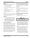
5. Place the image face down on a flat surface and
peel back the release liner on the leading edge
(about two inches).
6. Lay the image on the board and align it carefully.
When aligned, tack the exposed adhesive strip's
center to the leading edge to the board. Work
towards the edges from the center, being careful
not to wrinkle the image.
7. Position the piece so that the end with the liner
peeled back is facing the nip. Insert the first one
inch of the board into the nip. Very carefully, wrap
the print back and over the top laminating roll,
maintaining good print tension throughout the
mounting process. Be sure that there are no wrin-
kles in the nip area. Carefully peel off the liner as
the board progresses through the laminator.
8. Trim the board and image to the finished size.
-*.0/
2.1
This process is very similar to the Two Pass Mount and
Laminate using cold overlaminate.
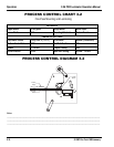
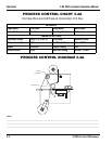
1. Adjust the machine settings as shown in process
chart 3-5a and remove the infeed table.
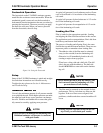
2. Web up the hot overlaminate by wrapping it around
the upper film idler and draping it over the upper
main roll. Drape the film only about halfway down
the upper main roll.
3. Pull the mount adhesive straight up from the lower
unwind position, being careful not to stick the film
to the machine. Tack it to the hot overlaminate.
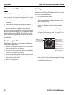
4. Insert a starter board into the nip and lower the
upper main roll onto it.
5. Press the footswitch. Once the leader board is
through the nip, lower the upper main roll and then
rotate the crank 1/2 a turn more.
6. Reinstall the infeed table.
7. Encapsulate the images.
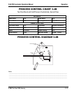
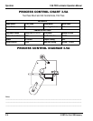
1. Adjust the machine settings as shown in process
chart 3-5b.
2. Trim the print to size and trim the board to the size
of the print.
3. Insert the board into the nip area and lower the
main roll until it contacts. Turn the crank another 1/
4 of a turn and remove the board using the foot-
switch.
4. Clean the board with a tack cloth or cleaning roller.
5. Place the image face down on a flat surface and
peel back the release liner on the leading edge
(about two inches).
6. Lay the image on the board and align it carefully.
When aligned, tack the exposed adhesive strip's
center to the leading edge to the board. Work
towards the edges from the center, being careful
not to wrinkle the image.
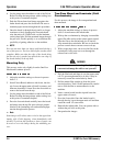
7. Insert the already mounted portion of the piece into
the pull roll nip. Lower the upper pull roll onto the
board and image. Very carefully, wrap the print
back and over the upper pull roll, maintaining good
print tension throughout the mounting process. Be
sure that there are no wrinkles in the nip area.
Carefully peel off the liner as the board progresses
through the laminator. Be careful not to hit the
small lip on the fan bridge to avoid damaging the
leading edge of the mounted image.
8. Trim the board and image to the finished size.