


ASTAT
®
-IBP Plus Service Instructions
Prices and data subject to change without notice. 7
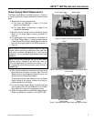
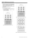
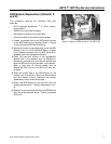
SCR Module Replacement (Sizes M, Z,
and N)
This procedure requires the following tools and
materials:
• #2 Philips-head screwdriver,
3
/16" Allen wrench,
torque wrench
• Scotchbrite or equivalent abrasive
• Mild solvent to clean mounting surfaces
• Electrolube 2GX or equivalent thermal grease
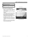
1. Loosen the screws holding the MOVs and bus bars
to the SCR Module to be replaced, shown in Figure
14, and remove the MOVs and bus bars.
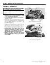
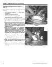
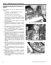
2. Remove the mounting screws at each end of the SCR
Module, then lift out the Module. Retain all parts
and hardware removed from the SCR Module for
reassembly with the replacement Module.
3. Clean the heat sink surface of the replacement
Module with a fine abrasive, such as Scotchbrite.
Remove all particles from the heat sink surface and
wipe the SCR mounting surface with a mild solvent.
Apply a light coat of thermal grease, such as
Electrolube 2GX to both the SCR and heat sink
surfaces.
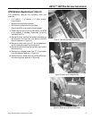
4. Place the contact face of the SCR Module on the
mating heat sink surface. Move the Module back
and forth several times to distribute the thermal
grease evenly over the contact surfaces.
5. Attach the SCR Module to the heat sink with the
screws removed earlier. Tighten the screws to 44 in-
lb.
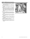
6. Reattach the bus bars and MOVs to the SCR Module
with the screws removed earlier. Tighten the screws
to 80 in-lb.
Figure 14. Location of SCRs on size M, Z, N ASTAT-IBP.