


ASTAT
®
-IBP Plus Service Instructions
Prices and data subject to change without notice. 5
Protection Board Replacement
1. Remove the following components:
a. The cover, as described in steps 1–2 of Cover
Removal and Replacement.
b. The Logic Board, as described in steps 2–3 of
Logic Board Replacement.
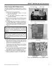
c. The Power Supply Board, as described in steps 2–
5 of Power Supply Board Replacement.
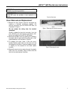
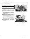
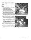
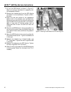
2. Remove the six wire connectors from the Protection
Board, as shown in Figure 11. Note the locations of
these terminals for reassembly.
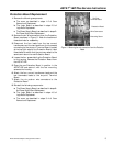
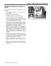
3. Disconnect the four leads from the two current
transformers and the two leads from the thermostat
connecting to the six-point Terminal Board, located
at the top-right edge of the Protection Board. Label
these leads to ensure that they are connected to the
same terminals on the new Protection Board.
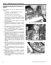
4. Loosen the four screws holding the Protection Board
to the housing. Remove the Protection Board from
the ASTAT-IBP.
5. Place the new Protection Board in position in the
ASTAT-IBP and secure it with the four mounting
screws to the housing.
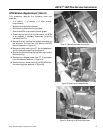
6. Attach the four current transformer leads and the
two thermostat leads to the six-point Terminal
Board.
7. Attach the six push-on wire connectors to the
Protection Board.
8. Reinstall the following components:
a. The Power Supply Board, as described in steps 6–
9 of Power Supply Board Replacement.
b. The Logic Board, as described in steps 4–5 of
Logic Board Replacement.
c. The cover, as described in steps 3–4 of Cover
Removal and Replacement.
Figure 11. Removing the wire connectors from the Protection
Board.
Six-Point
Terminal Board
Protection Board
Wire Connectors
Mounting Screw