


ASTAT
®
-IBP Plus Service Instructions
Prices and data subject to change without notice. 11
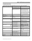
Troubleshooting Guide
This guide is provided for troubleshooting and isolating common problems. It does not cover every possible situation.
Contact the Customer Support Center at 800-843-3742 if any problem is not resolved by these procedures.
Symptom or Error & (Error Code)Symptom or Error & (Error Code) Possible CausePossible Cause Measures to Be TakenMeasures to Be Taken
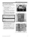
No control voltage.
Main breaker tripped or fuse blown
Check wire harness and control voltage
F1 fuse blown on power supply PCB Check and change.
Display OFF
Bad connection of flat ribbon wire
joining power supply PCB to control
PCB
Verify connectors.
Check power supply board and logic
board for 5VDC. Use a DC voltmeter on
the power supply board, (-) lead of
voltmeter on the top lead of C6 (located
next to the black heatsink on the right
edge of the power supply board) and the
(+) lead of voltmeter on top lead of Diode
AD21 or R25 (located on the upper right
corner of the power supply board.)
Equipment does not respond to STOP /
START controls
F2 fuse blown on power supply PCB Check and change.
Frequency error (admits
45Hz ≤ f main ≤ 65Hz) (Ex10)
No 1L11L1 phase or frequence is out of
range
Check 1L11L1 phase and/or mains
frequence
Overload trip (Ex11) Excessive load or excessive current
during starting
Verify overload conditions during starting
time and steady state. Check settings in
parameters "Nxxx", "Lxxx", and "oxxx"
Synchronism loss (Ex13) Phase 1L1 1L1 lost Check 1L11L1 phase
Short circuited thyristor Check thyristor module.
Check ground connections and voltage to
ground.
Poor ribbon cable connection
Phase A, B, C thyristor (Ex14)
(Ex15)
(Ex16)
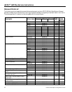
No output phases Check 2T1, 4T2 2T1, 4T2 and 6T3 6T3 phases
Heatsink thermostat (Ex17) Heatsink thermostat tripped by
overheating or defective
Check for adequate ventilation.
Check thermostat and wiring
Motor thermistor(Ex18) Motor thermistor tripped by
overheating or defective
Check thermistor and wiring, if no
thermistor terminal 5 and 6 must be
jumpered
No input / output phases Check power wire harness for 1L1,1L1,
3L2, 5L3, 2T1, 4T2 3L2, 5L3, 2T1, 4T2 and 6T36T3
Phase A, B, C loss (Ex19)
(Ex20)
(Ex21)
Defective thyristor or ribbon wire
harness loose or defective
Verify gate and cathode wire harness.
Verify thyristors
Stalled rotor (Ex22) Equipment detected stalled motor
rotor
Restart equipment and check for an
appreciable loss in motor speed at any
time
Internal error (Ex23) Micro-controller malfunction Check IC1 and IC8 are correctly inserted
in their sockets.
Check for noise on control voltage power
or line
Long start time (Ex25) Current limit condition present more
than2 x ta sec. or 240 sec. (ta =
acceleration ramp time)
Increase current limit and / or acceleration
ramp time
Lock-out (Ex27) The time between startings is less
that the adjusted in parameter "LKxx"
Check if settings are correct.
This protection may be disabled
Undervoltage (Ex28)
Overvoltage (Ex29)
The line voltage exceeds of limit set in
parameters "UVxx" or "OVxx"
Check if settings are correct.
This protection may be disabled
Undercurrent (Ex30)
Overcurrent (Ex31)
The motor current exceeds of limit set
in parameters "UCxx" or "OCxx"
Check if settings are correct.
This protection may be disabled