


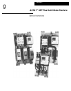


ASTAT
®
-IBP Plus Service Instructions
2 Prices and data subject to change without notice.
Logic Board Replacement
CAUTION: Always handle circuit boards by their edges
and do not distort the parts on the circuit boards.
ATTENTION: Il faut toujours manipuler les plaques de
circuits par leurs côtés et ne pas déformer les pièces sur
les plaques de circuits.
1. Remove the ASTAT-IBP cover as described in steps
1–2 of Cover Removal and Replacement.
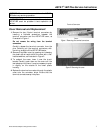
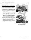
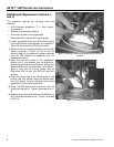
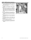
2. Unplug the two ribbon cables from the Logic Board,
as shown in Figure 3.
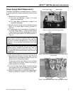
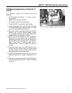
3. Remove the four corner screws holding the Logic
Board to the stand-offs below the Logic Board. Lift
the Logic Board straight up to remove it, as
illustrated in Figure 4.
4. Reassemble the Logic Board to the starter. With the
display on the Logic Board at the upper left corner,
place the board on the stand-offs. Reattach the four
screws holding the Logic Board to the stand-offs.
5. Reattach the two ribbon cables. Ensure that the
ribbon cable at the bottom of the ASTAT-IBP is fully
seated on both circuit boards and that the ribbon
cable does not interfere with or touch the cover.
6. Reinstall the plastic cover and the terminal
connectors as described in steps 3–4 of Cover Removal
and Replacement.
Figure 3. Logic board and part locations.
Figure 4. Removing the Logic Board.
Screws
Logic Board
Power Supply
Board
Unplug Cable
Ribbon
Logic Board
Cable Ribbon