


ASTAT
®
-IBP Plus Service Instructions
Prices and data subject to change without notice. 9
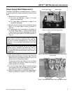
SCR Module Replacement (Size S)
This procedure requires the following tools and
materials:
•
9
/16" wrench,
11
/16" wrench,
3
/16" Allen wrench,
torque wrench
• Scotchbrite or equivalent abrasive
• Mild solvent to clean mounting surfaces
• Electrolube 2GX or equivalent thermal grease
1. Disconnect the control wiring harness for the SCRs
to be replaced. If necessary, disconnect the wiring
harness of the CTs.
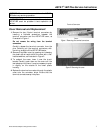
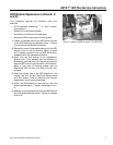
2. Remove the bolt holding the busbars connected to
the blocks on the load and line sides of the SCR
Module, as shown in Figure 18.
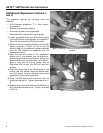
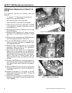
3. Remove the bolt holding the CT, the threaded stud,
and the load-side busbar from the Module.
4. Remove the bolts holding the load-side lug in place.
Remove the lug.
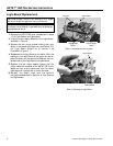
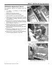
5. Remove the L-shaped busbar and CT, if applicable,
from the assembly, as shown in Figure 19.
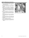
6. Remove the four screws holding the SCR Module to
the mounting plate, as shown in Figure 20.
Figure 18. Removing the busbar mounting bolt.
Figure 19. Removing the L-shaped busbar.
Figure 20. Removing the SCR mounting screws.