


POWER LEADER™ Ethernet Gateway
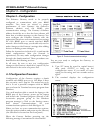
Chapter 3 – Configuration
12
Network Test – FACTORY USE ONLY
NOTE: A client program may be requested from GE to
run on the host when performing the network test. The
client attempts to establish a connection to a server (the
Gateway) with the specified IP address, subnet mask and
port number.
Menu item 5 is for factory testing of the network.
End users should NOT select this option. This test
attempts to communicate with a host across the
Ethernet. To complete this test, you will need an
RS232 null modem cable, available at an electronics
retailer. Before performing this test, the host PC
must be running the client software mentioned
above, and must be connected to the Ethernet
Gateway via the null modem cable.
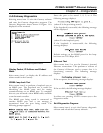
When you select menu item 4, the following
message is displayed:
If the network test passes, the following message is
displayed:
If the network test fails, the following message is
displayed:
In either case, pressing <ENTER> returns you to the
diagnostics menu.
3–7 Advanced Options – Technical
Support Personnel ONLY
Ordinarily these options will have been configured
by the system integrator or direct from the factory;
you should NOT alter any of the settings from the
advanced options area of the Configuration menu.
WARNING: ALTERING ANY OF THESE SETTINGS
MAY RENDER THE ETHERNET GATEWAY
INOPERABLE. IF YOU ACCIDENTALLY SELECT ANY
OPTION FROM THE ADVANCED SETTINGS, PRESS
<ESC> TO EXIT, THEN PRESS <ENTER> TO RETURN
TO THE CONFIGURATION MENU.
Select menu item 15 to modify the Gateway socket
identifier. The format is: ####.
Select menu item 16 to modify the Gateway Internet
Protocol (IP) address. Enter the IP address in dot
notation, e.g., 123.145.51.126.
Select menu item 17 to modify the Gateway subnet
mask. Enter the subnetwork mask in dot notation,
e.g., 255.255.255.0.
Select menu item 18 to modify the FTP PC/TCP
kernal serial number. The number has the
following format: 1234-5678-9012.
Select menu item 19 to modify the FTP PC/TCP
kernal authentication key. The number has the fol-
lowing format: 1234-5678-9012.
Select menu item 21 to modify the Gateway Router.
This item has the following format: 0.0.0.0, 0.0.0.0,
0.0.0.0 Note that the Router numbers may have
multiple digits in each placeholder, and each set of
four numbers represents one router; for example,
205.109.43.11, 0.0.0.0, 0.0.0.0 is configured for one
router. The Gateway may be configured with a
maximum of three routers.
Updating the Gateway Software
Option 20 of the Configuration menu allows updat-
ing of the Ethernet Gateway’s operating software
and is for use ONLY by factory service personnel.