


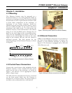


POWER LEADER™ Ethernet Gateway
Chapter 5 – Errors and Diagnostic Messages
14
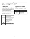
Chapter 5 – Diagnostic Messages and Errors
5–1 Monitor Mode
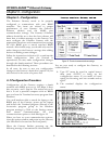
The Ethernet Gateway can be set to send diagnostic
messages to the RS232 port to be displayed on a
terminal (see Chapter 3). These diagnostic
messages can be very useful in tracking down errors
in configuration or device addressing.
Diagnostic messages sent to the RS232 port in moni-
tor mode have the following format:
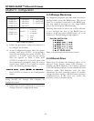
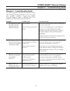
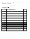
Table 6 explains what each field means:
Field Meaning
The relative time of the message in timer
ticks. This rolls over every
1,000,000,000 timer ticks.
Indicates the direction of the message:
E-n (n = 1,2,3 or 4) indicates a message
sent from the Ethernet Gateway to
RS485 port number 1,2,3 or 4
n-E indicates a message sent from
RS485 port number 1,2,3 or 4 to the
Ethernet Gateway
Header byte added to regular Modbus
message. Printed as two hex digits.
Binary data of regular Modbus message.
Printed as two hex digits.
Table 6. Diagnostic messages key.
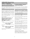
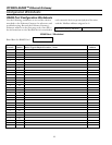
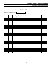
5–2 Processing Error Messages
Table 7 gives error messages that may be generated
by the Gateway and displayed at the PMCS host.
Message Meaning
Error - Buffer Overflow One or more buffers have
overflowed.
Error - Writing to Flash
ROM
An attempt to write to flash ROM
(drive A) has failed.
Error - Reading Flash
ROM
An attempt to read the flash ROM
(drive A) has failed.
Table 7. Error message key.