


POWER LEADER™ Ethernet Gateway
Chapter 2 – Installation
5
Chapter 2 – Installation
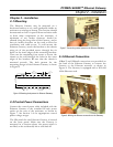
2–1 Mounting
The Ethernet Gateway may be mounted on a
horizontal surface or on a wall, preferably inside an
enclosure or switchgear lineup. The Gateway should
be mounted so that it is spaced from enclosure walls
or from other components in the enclosure. A
minimum of two inches clearance should be
allowed along the long sides of the Gateway, and at
least six inches clearance on the ends to allow for
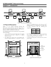
ventilation and cable access. To wall mount the
Ethernet Gateway, attach the brackets to the chassis
using six of the provided screws through the six
holes on the inner edges of the mounting brackets.
Then use the remaining four screws to secure the
chassis to the wall through the holes in the outer
edges of the brackets. Be sure that the chassis is
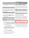
mounted securely. The hole pattern for the
mounting flanges of the Ethernet Gateway is shown
in Figure 6.
8 - R5 4 - R2.5
12 in. 1 in.
7 - 1/8"
190.6 mm
305.0 mm 23.0 m
m
Figure 6. Mounting hole pattern for Ethernet Gateway.
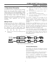
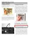
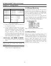
2–2 Control Power Connections
Connect the control power cable included with the
Ethernet Gateway to the standard PC-style power
outlet on the rear of the enclosure, as shown in
Figure 7. See Section 1–4 for appropriate control
power voltage ranges.
The ON switch for the Ethernet Gateway is located
on the front panel. Make sure the Gateway is
mounted in a location where the power switch is
not likely to be accidentally hit or switched off.
Figure 7. Connecting control power to the Ethernet Gateway.
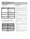
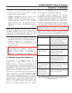
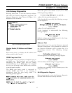
2–3 Ethernet Connection
10BaseT and 10Base2 connections are provided on
the back of the Ethernet Gateway to connect the
Gateway to the Ethernet network, as shown in
Figure 8. The Gateway is equipped with a PCL-843
16-bit Ethernet card.
Figure 8. Making the Ethernet connection to the Gateway.