


POWER LEADER™ Ethernet Gateway
Table of Contents
ii
List of Figures
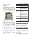
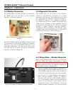
Figure 1. POWER LEADER Ethernet Gateway. ............................................................................................1
Figure 2. Typical use of Ethernet Gateway. ................................................................................................... 2
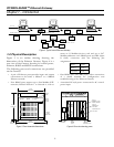
Figure 3. Front view of Ethernet Gateway, showing dimensions. ................................................................2
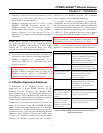
Figure 4. Rear view of the Ethernet Gateway, showing Ethernet, RS485 and RS232 ports........................2
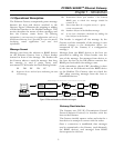
Figure 5. Ethernet headers on Modbus messages.........................................................................................3
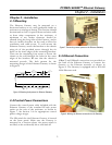
Figure 6. Mounting hole patter for Ethernet Gateway. ................................................................................5
Figure 7. Connecting control power to the Ethernet Gateway..................................................................... 5
Figure 8. Making the Ethernet connection to the Gateway. ........................................................................5
Figure 9. Connecting an RS485 network to the Ethernet Gateway..............................................................6
Figure 10. Termination of the RS485 network at the last Modbus device..................................................6
Figure 11. Connecting a dumb terminal to the RS232 port.........................................................................6
Figure 12. Terminal communications settings. ............................................................................................ 8
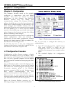
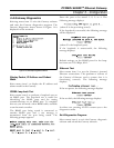
Figure 13. Ethernet Gateway configuration menu........................................................................................8
Figure 14. Gateway diagnostics menu.......................................................................................................... 11
List of Tables
1. Examples of Modbus RTU compatible devices. .......................................................................................1
2. POWER LEADER Ethernet Gateway specifications. ................................................................................ 4
3. POWER LEADER Ethernet Gateway environmental requirements........................................................ 4
4. POWER LEADER commnet devices supported by the Modbus Concentrator......................................7
5. RS485 Port Settings....................................................................................................................................10
6. Diagnostic messages key............................................................................................................................ 14
7. Error message key...................................................................................................................................... 14