


POWER LEADER™ Ethernet Gateway
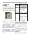
Chapter 1 – Introduction
2
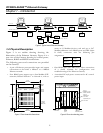
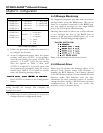
Ethernet
Gateway
Host
PMCS
Ethernet
PLC
90/30
Multilin
565
Modbus
Concentrator
PLC
90/70
Multilin
269+
EPM
3710
EPM
3720
Other
PC
Other
PC
POWER
LEADER
Meter
MVT-PM
Trip Unit
Spectra
E CM
PLEPM
RS485 Modbus RTURS485 Modbus RTU
commnet devices
Figure 2. Typical use of Ethernet Gateway.
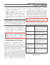
1–2 Physical Description
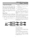
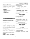
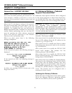
Figure 3 is an outline drawing showing the
dimensions of the Ethernet Gateway. Figure 4 is a
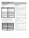
rear view of the Gateway showing its control power,
Ethernet, RS485 and RS232 connections.
The following ports and connections are provided
on the Gateway:
• A pair of Ethernet ports provides input and output
connections to the either a 10BaseT or a 10Base2
Ethernet network.
• Four RS485 ports support up to four Modbus RTU
networks, labeled Network 1 to Network 4, with as
many as 31 Modbus devices each and up to 247
Modbus addresses each. RS485 ports are DB-9 (9-pin
D shell) connectors with the following pin
assignments:
Data - Pin 1
Data + Pin 2
Ground Pin 5
• One RS232 port (also DB-9 style) allows connection
of a dumb terminal for configuration and
troubleshooting of the Ethernet Gateway.
• A standard PC-style power connector for AC control
power input.
0.32 in.
8.0 mm
Power
on/off
switch
Power
HDD Reset
Status
LEDs
6.7 in.
170.0 mm
7.32 in.
196.0 mm
7.5 in.
166.0 mm
Length:
15.5 in.
393.0 mm
Figure 3. Front view with dimensions.
Control power
connection
Four
RS485
ports
10Base2 and
10BaseT
Ethernet ports
Com 1
RS232 port for
dumb terminal
1
2
3
4
Com 2
RS232 port
not used
keyboard port
not used
Figure 4. Rear view showing ports.