


POWER LEADER™ Ethernet Gateway
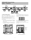
Chapter 1 – Introduction
3
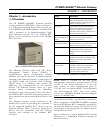
1-3 Operational Description
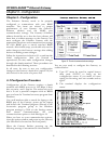
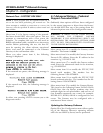
The Ethernet Gateway transparently passes message
between the host and devices attached to the
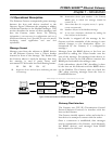
Gateway. Figure 5 illustrates the stripping or adding
of Ethernet headers to the Modbus messages. This
section describes the nature of these messages and
how the Gateway routes them. The following
information is not necessary for configuration and use of
the Ethernet Gateway, but is provided for users who may be
developing custom applications and need such
information.
Message Format
Messages sent from the software to RS485 devices
via the Ethernet Gateway have a 15-byte header
inserted in front of the message. The header tells
the Gateway where to send the message, how long
the message is, and if parity errors were
encountered. This header has the following format:
SS DD EE NN CC
SS Sequence of ten AA hex bytes indicating the start
of a message
DD Destination device port number – the Gateway
RS485 port to which the message should be
routed (0 - 3)
EE Error status byte (0 = no parity errors, 1 = parity
errors encountered)
NN Number of bytes in the Modbus message
CC A one byte checksum calculated by adding the
first 14 bytes in the header
The header is stripped off the message by the
Gateway and the remainder of the message is sent
without changes to the destination device (or
interpreted by the Gateway if a configuration
message).
Messages from the RS485 devices to the host are
processed by adding the 15-byte header onto the
start of the message. For messages from devices to
the host, the byte in the DD position contains the
RS485 port from which the message came.
Cyclic redundancy check (CRC) handling is done
by the host on the Ethernet and the RS485 device
on the Modbus. The Gateway does not check the
CRC when receiving messages from the host or
from RS485 devices.
Ethernet
header
information
Modbus
message
Host
PMCS
Modbus
message
Ethernet
header
information
Modbus
message
Modbus
message
Modbus messages from host to device - Ethernet Gateway strips off header
Modbus messages from device to host - Ethernet Gateway adds header
Message traveling on Ethernet
Message traveling on RS485
Ethernet
Gateway
Ethernet
Gateway
RS485
device
RS485
device
Figure 5. Ethernet headers on Modbus messages.
Gateway/Host Interface
The Gateway uses TCP/IP (Transmission Control
Protocol/Internet Protocol) to interface with the
host on the Ethernet.
The Gateway initially opens a socket and waits for a
host device to attempt to connect with the socket.
Once a connection is established, data messages
may be transmitted to the Gateway (and ultimately
the RS485 devices) and messages from RS485
devices passed to the host.