


GA-M59SLI-S5/GA-M59SLI-S4 Motherboard - 30 -
English
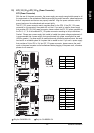
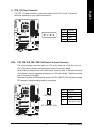
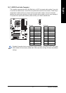
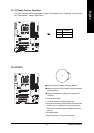
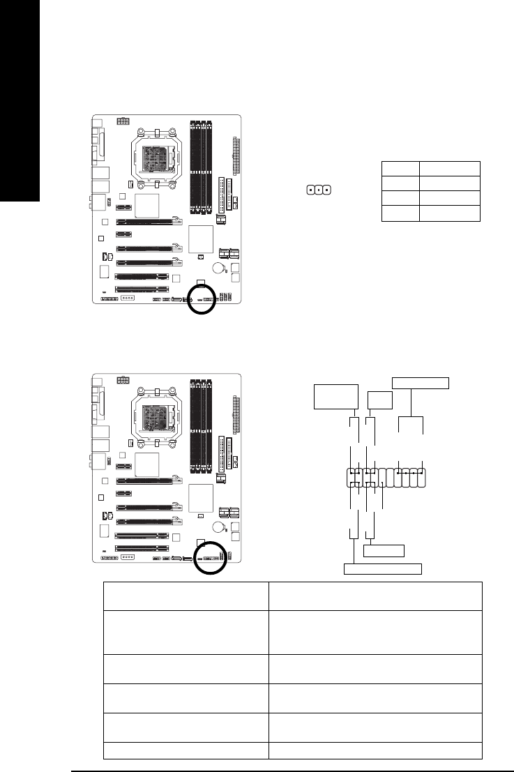
13) F_PANEL (Front Panel Jumper)
Please connect the power LED, PC speaker, reset switch and power switch etc of your chassis
front panel to the F_PANEL connector according to the pin assignment below.
1
2
19
20
HD-
HD+
RES+
RES-
NC
IDE Hard Disk Active LED
Reset Switch
SPEAK-
MSG-
MSG+
PW-
PW+
Message LED/
Power/
Sleep LED
Speaker Connector
SPEAK+
Power
Switch
HD (IDE Hard Disk Active LED) Pin 1: LED anode(+)
(Blue) Pin 2: LED cathode(-)
SPEAK (Speaker Connector) Pin 1: Power
(Amber) Pin 2- Pin 3: NC
Pin 4: Data(-)
RES (Reset Switch) Open: Normal
(Green) Close: Reset Hardware System
PW (Power Switch) Open: Normal
(Red) Close: Power On/Off
MSG (Message LED/Power/Sleep LED) Pin 1: LED anode(+)
(Yellow) Pin 2: LED cathode(-)
NC ( Purple) NC
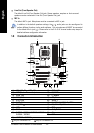
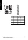
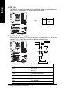
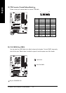
12) PWR_LED
The PWR_LED connector is connected with the system power indicator to indicate whether the
system is on/off. It will blink when the system enters suspend mode.
Pin No. Definition
1 MPD+
2 MPD-
3 MPD-
1