


Installation
4 313212A
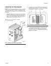
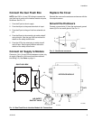
Install the Cable
1. Loosen the captive screws and remove the front
cover from the enclosure.
2. The cable (23) has bare wires at both ends. Thread
the shortest end (4 in. [102 mm]) into the enclosure
through the strain relief bushing (7). See F
IG. 2.
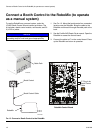
3. Connect the cable wires to the left side of the termi-
nal strip (12), as indicated by the label (20). See F
IG.
2 and Table 1.
4. Connect the other end of the cable (5 in. [127 mm])
to pins 1-4 and 7-10 of the 10 position connector
(24) and pins 1-4 of the 6 position connector, as
shown in the Cable (23) Wire Harness Detail on
page 11.
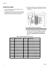
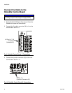
F
IG. 2. Connect Cable to Terminal Strip
20 12
TI14279a
7
Table 1: Terminal Strip Wire Connections
Pin No. Cable Wire Colors Pin No. Switch Wires
1 Black 1 Air Flow Switch 1 +
2 White 2 Air Flow Switch 1 -
3 Red 3 Air Flow Switch 2 +
4 Green 4 Air Flow Switch 2 -
5 Orange 5 Pressure Switch 1 +
6 Blue 6 Pressure Switch 1 -
7 White/Black 7 Pressure Switch 2 +
8 Red/Black 8 Pressure Switch 2 -
9 Green/Black 9 Solenoid 1, + (12V), Red
10 Orange/Black 10 Solenoid 1, - (COM), Black
11 Blue/Black 11 Solenoid 2, + (12V), Red
12 Red/White 12 Solenoid 2, - (COM), Black