


Installation
313212A 5
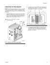
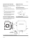
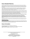
Install the Air Flow Switch
NOTE: The GFB Interface Module Kit does not include
an air flow switch (AFS). The AFS is supplied with the
gun flush box kit. Install the AFS in the interface module
as follows.
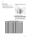
1. Each gun flush box kit includes one air flow switch
(AFS). The GFB interface module can accommo-
date 1 or 2 air flow switches. Install the switch(es) in
the right side of the enclosure. See F
IG. 3.
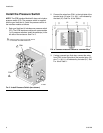
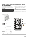
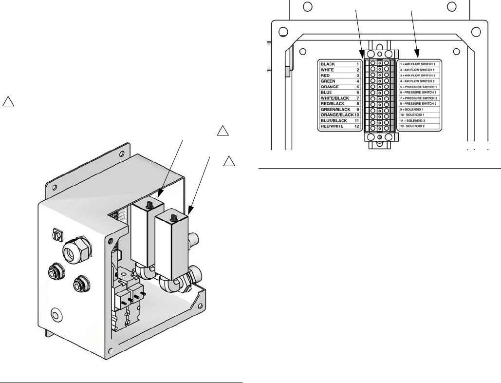
2. Connect the wires from AFS#1 to the right side of
the terminal strip (12) pins 1 (+) & 2 (-), as indicated
by the label (21). See F
IG. 4 and Table 1.
3. If using a second gun flush box, connect the wires
from AFS#2 to the right side of the terminal strip
(12) pins 3 (+) & 4 (-), as indicated by the label (21).
See F
IG. 4 and Table 1.
F
IG. 3. Install Air Flow Switch (two shown)
AFS#1
AFS#2
TI14281a
AFS is part of gun flush box kit; not included
with GFB Interface Kit.
1
1
1
FIG. 4. Connect Air Flow Switch to Terminal Strip
2112
TI14279a