


Installation
313212A 7
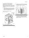
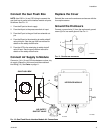
Install the Solenoid
NOTE: The GFB Interface Module Kit does not include a
solenoid (SO). The solenoid is supplied with the gun
flush box kit. Install the solenoid in the interface module
as follows.
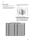
1. Each gun flush box kit includes one solenoid (SO).
The GFB interface module can accommodate 1 or 2
solenoids. Install the solenoid(s) on the manifold at
the bottom rear of the enclosure. See F
IG. 7.
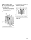
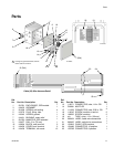
NOTE: See Parts on page 11. If you are using two gun
flush boxes, remove the two sealing screws (4) from the
solenoid manifold (8) before installing SO#2. Also
remove the plug (5) from the connector (15).
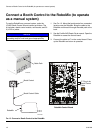
2. Connect the wires from SO#1 to the right side of the
terminal strip (12), as indicated by the label (21); red
(+12V) to pin 9, black (COM) to pin 10. See F
IG. 8
and Table 1.
3. If using a second gun flush box, connect the wires
from SO#2 to the right side of the terminal strip (12),
as indicated by the label (21); red (+12V) to pin 11,
black (COM) to pin 12. See F
IG. 8 and Table 1.
F
IG. 7. Install Solenoid (two shown)
SO#1
SO#2
TI14282a
Solenoid is part of gun flush box kit; not
included with GFB Interface Kit.
1
1
1
FIG. 8. Connect Solenoid to Terminal Strip
2112
TI14279a