


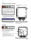
Installation
14 313855H
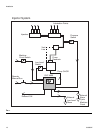
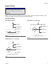
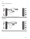
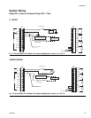
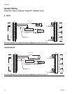
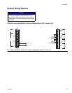
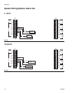
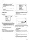
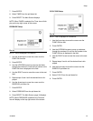
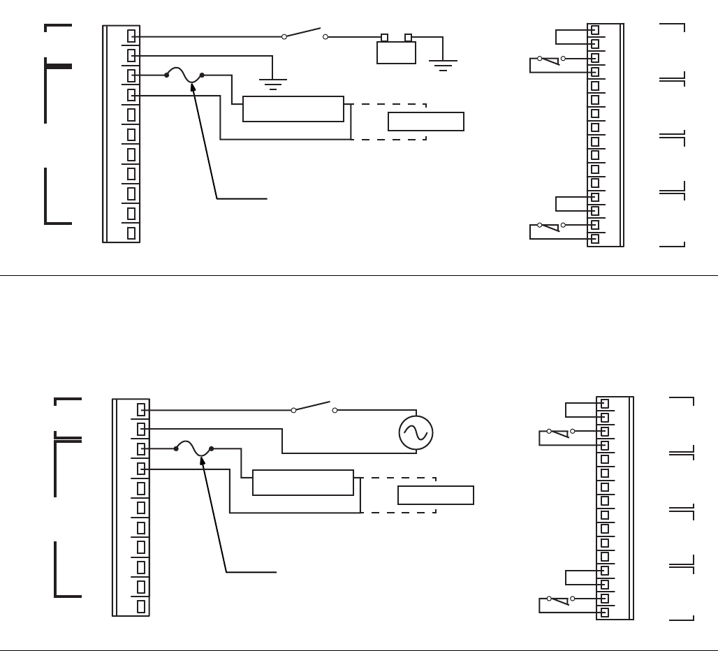
System Wiring
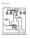
Pump ON = Cycle or Pressure; Pump OFF = Machine Count
9 - 30VDC
100VAC/240VAC
FIG. 15 Dry Contact, FIG. 8 shown. For other configuration, see FIG. 9 or FIG. 10.
F
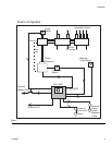
IG. 16 Dry Contact, FIG. 8 shown. For other configuration, see FIG. 9 or FIG. 10.
5A max.
16 (SW-)
15 (SEN4)
14 (IN4)
13 (SW+)
12 (SW-)
11 (SEN3)
10 (IN3)
9 (SW+)
8 (SW-)
7 (SEN2)
6 (IN2)
5 (SW+)
4 (SW-)
3 (SEN1)
2 (IN1)
1 (SW+)
1(IN)
2(COM)
3(OUT1)
4(COM)
5(OUT2)
6(COM)
7(OUT3)
8(COM)
9(OUT4)
10(OUT4)
11
OUTPUTS
-PWR+
J6J7
+
Ignition Switch
Manual
Low
Level
Press/
Cycle
Count
(Voltage = Battery Voltage)
Pump Solenoid
9 - 30 VDC Battery
Dry Contact Switch
Dry Contact Switch
*
*
NC
Air or Hydraulic Solenoid
Pump Power or Motor
+
Electric Vent Valve
10A max.
16 (SW-)
15 (SEN4)
14 (IN4)
13 (SW+)
12 (SW-)
11 (SEN3)
10 (IN3)
9 (SW+)
8 (SW-)
7 (SEN2)
6 (IN2)
5 (SW+)
4 (SW-)
3 (SEN1)
2 (IN1)
1 (SW+)
1(IN)
2(COM)
3(OUT1)
4(COM)
5(OUT2)
6(COM)
7(OUT3)
8(COM)
9(OUT4)
10(OUT4)
11
OUTPUTS
-PWR+
J6J7
Ignition Switch
Manual
Low
Level
Press/
Cycle
Count
100-240 VAC
(Voltage = Line Voltage)
Pump Solenoid
Dry Contact Switch
Dry Contact Switch
*
*
NC
Air or Hydraulic Solenoid
Pump Power or Motor
Electric Vent Valve