


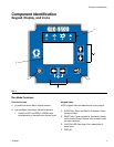
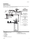
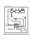
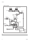

Component Identification
4 313855H
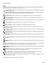
Icons
The following icons are used throughout this instruction manual and on the Controller’s Run and Setup Screens.
Refer to this table if you are unsure of an Icon’s meaning.
*See Field E, page 3 for location of these Function Icons.
Power on indicator*. When power is supplied to the Lubrication Controller, Green LED illuminates under Function Icon
located above display screen.
Pump On indicator*. When Pump On is running, Yellow LED illuminates under Function Icon located above display
screen. Icon also is displayed on top left side of Prelube Run screens (see page 30).
Pump Off indicator. When Pump Off is running, icon is displayed on top left side of Run screens (see page 31).
Alarm event activated. LED illuminates when an Alarm event occurs. Icon also displays on top right side of Alarm
screen (see page 32).
Brightness adjustment. Use the LEFT/RIGHT Arrow key to adjust display backlight (brighter or darker) (see page 17).
Contrast adjustment. Use the UP/DOWN Arrow key to adjust screen contrast (see page 17).
Low Level Alarm. Icon appears on display screen. Indicates the lubrication fluid level is low.
Change Icon. When icon appears on PIN setup screen, indicates changes can be made to PIN number or new PIN
number can be added.
Lock Icon. Indicates the Setup screens are password protected and require the user to provide the correct PIN number
to access this feature.
Setup mode active. When user is on the Main Setup Screen in the Setup Mode, icon displays on the upper right corner
of the display screen.
Timer mode activated. Displays on right side of screen when a Timer Setup or Run screen is displayed (pages 18, 21,
30 and 31).
Pressure mode activated. Icon displays on right side screen when a Pressure Setup or Run screen is displayed (page
19 and 30).
Pressure mode error. Icon displays on alarm screen to signal the allotted time ran out before the pressure switch was
tripped.
Cycle count mode active*. Yellow LED illuminates under Function Icon located above display screen. Icon also appears
on right side of display screen when a Cycle Setup or Run screen is displayed (page 19 and 31).
Machine count active. Displays on right side of Setup or Run screen when a Machine Count screen is displayed (page
21 and 32).
Machine count error. When icon displays on alarm screen, indicates the set number of machine counts was not
received before time expired (page 32). This would trigger an alarm event.
Cycle switch input error. Icon displays in center of Alarm screen to indicate the allotted time ran out before the
programmed number of cycle switch activations was received (see Alarm Screen, page 32).
Alarm*. Red LED illuminates under symbol located above display screen. Icon also appears on display when no valid
run values have been entered.