


1
Copyright 2007
Hearth & Home Technologies Inc.
20802 Kensington Blvd., Lakeville, MN 55044
130-911G 12/07
WSK-MLT MULTIFUNCTION WALL SWITCH
- INSTALLATION AND OPERATING INSTRUCTIONS -
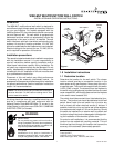
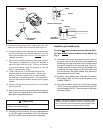
Figure 1.
Introduction
The WSK-MLT multifunctional wall switch is designed to
control fl ame height, blower speed, and auxiliary functions
on your gas fireplace. For models equipped with the
Intellifi re system (IPI), the cold climate function can control
the pilot fl ame as well. The wall switch is equipped with
thermostat functions which can automatically control the
temperature in the room in which it is installed. The wall
switch interfaces with both intermittent and standing pilot
systems. An auxiliary function provides 110-120 VAC
source for added features the fi replace may have installed.
Electrical ratings for the control box are 110 VAC, 60 Hz,
and is required for operation of this device.
Installation precautions
This remote is tested and safe when installed in accordance
with this installation manual. It is your responsibility to
read all instructions before starting installation and to
follow these instructions carefully during installation. Do
not install any components that may be damaged. Do not
modify, disassemble, or substitute any of the components
included with this kit. Installation of this unit must be done
by a qualifi ed service technician.
Placement of this wall switch may affect performance
or accuracy of the automatic (thermostat) control. An
assessment of the space should be done prior to installation
for optimal performance. See the installation instructions
section I for recommendations.
1.0 Installation instructions
1.1 Determine location
Determine the location for the wall switch. The chosen
location should provide an accessible location in the
same space as the gas fi replace. Never place this unit in
a separate room. The control wire supplied with this switch
is 33 ft (10M) in length. The distance from the fi replace to
the switch may be lengthened provided that the wire used
never exceeds 50 ft, and that the distance from the fi replace
to the switch never exceeds 30 ft.
The switch should be mounted into a listed electrical junc-
tion box. The junction box should be dedicated to this wall
switch. Never install this wall switch into a junction box
that is shared with other electrical service or devices. If
possible, install this unit on an interior wall of the residence
at a recommended height of 5 ft from the fl ooring. Should
the switch be installed on an exterior wall, be certain wall
insulation is kept intact and not damaged or dislodged dur-
ing the installation of the electrical junction box.
For exterior wall installations, it is recommended that the
junction box be sealed with caulking material. This will
minimize heat loss through this location and improve the
accuracy of the automatic (thermostat) operation.
WARNING
Shock Hazard
Do not provide any power to this unit until all
wiring is completed. Failure to do so may destroy
parts of this device and render it unusable, and
may lead to possible electrical shock.
Fire Hazard
Modification of any parts or installation of
damaged components will void the warranty,
and you may possibly cause a fi re hazard.
NOTE: The electrical junction box provided with the fi replace
must be wired with 110 VAC before installing this kit. See
owners manual for details.
All wiring should be done by a qualifi ed electrician and
shall be in compliance with local codes and with the
National Electric Code ANSI/NFGA No. 70- current (in the
United States), or with the current CSA C22.1 CANADIAN
ELECTRIC CODE (in Canada).
CONTROL
BOX
CONTROL
WIRE
WALL SWITCH
COVER
PLATE
FLAME
SOLENOID