


5
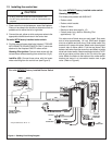
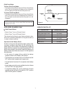
VARIABLE
REGULATOR
GAS CONTROL
VALVE
FLAME CONTROL
SOLENOID
KNOB
SCREW
NUT
VARIABLE REGULATOR
JAM NUT
VARIABLE
REGULATOR
SOLENOID
WASHER
WASHER
PLUNGER
Figure 6.
Intellifi re (ipi) models only
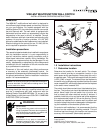
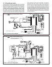
For units with factory installed rocker switch see Fig. 3.
For units without factory installed rocker switch see
Fig. 5.
14. Disconnect main valve wire (green) from the front of
the valve. Connect red control wire to red adapter wire
containing one large male end and one small female
end and connect to valve terminal (see Figure 3).
Connect the other red control wire to red adapter wire
containing one large female end and one small male
end and connect the green module wire (previously
disconnected from valve front).
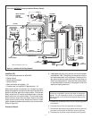
15. Carefully unplug battery pack wires from IPI module.
Plug battery pack into red and black battery wires
(labeled “Battery”).
16. Plug red and black wires from control box (labeled
“3V DC”) to the red and black wires extending from IPI
module (labeled “3V DC”). Red connects to red, black
connects to black.
9. Insert the correct plunger (blue - natural gas, red - pro-
pane) into the fl ame control solenoid (see Figure 6).
10. Thread the fl ame control solenoid with correct plunger
into the thread hole in the variable regulator. Turn into
valve approximately two full turns. Do not tighten or
damage may occur.
11. Set the valve manifold pressure to the proper setpoint.
The setpoint is adjusted by rotating the solenoid to
adjust its depth into the valve. Using a manometer
to monitor pressure, rotate the solenoid so that the
output is set to proper range.
12. Tighten the jam nut on the threaded shaft of the
solenoid against the valve regulator. Use an open-
ended ½” wrench to tighten the nut, while holding
the solenoid in the proper position. This step will en-
sure that the solenoid remains locked into the proper
position.
13. Connect orange wires from control box to the fl ame
control solenoid.
14. Ground the control box by attaching the green ground
wire (has round ring-terminal on end) to the fi replace
base pan or appropriate ground.
13. Connect auxiliary functions. This unit is equipped with
a 110 VAC supply cord (labeled “AUX”) for controlling
auxiliary functions such as an electric ember bed.
Lay the control box and wires fl at on the base pan to avoid
potential overheating problems.
NOTE: Transformer supplied with the IPI system is NOT
used. Disconnect the transformer from the electrical junction
box. Transformer may be removed from the fi replace, but we
recommend leaving it connected to the IPI module.
CAUTION