


3
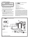
1.3 Installing the control box
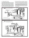
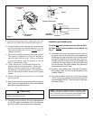
Figure 4. Standing Pilot Wiring Diagram
For units WITHOUT factory installed Rocker Switch
Standing Pilot Ignition:
Find these parts packed with WSK-MLT:
• Rocker switch
• Rocker switch bracket
• Strips of Velcro
• Black and white wire pigtails - (2)
• Female ends (only used on Standing Pilot
applications) - (2)
Cut male ends off black wires on each pigtail. Strip each
end of wire approximately 1/4 inch. Slide each stripped
wire into a female end and crimp. Slide rocker switch into
bracket until it snaps into place. Attach end of each pigtail
to each side of rocker switch. Find the top (brown) and
bottom (red) wires from the control box and attach to white
wires from rocker switch. Attach one black wire to the TH/TP
side of gas valve and the other to the TH side of the gas
valve. Attach the Velcro to the bottom of the rocker switch
bracket and mount in a convenient location next to gas
valve. (Refer to Figure 4).
For units WITHOUT factory installed rocker switch.
1. Place control box into the base pan area of the fi replace.
Place unit as close to the louvers or decorative front as
possible and to either the left or right side.
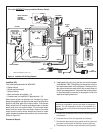
2. Connect the red, yellow or white, and green wires to the
appropriate labeled terminals on the control box.
For units WITH factory installed rocker switch.
3. Find the red and brown pigtail wire (labeled “ FOR USE
WITH REMOTE OR WALL SWITCH ONLY”) which are
attached to the fi replace ON/OFF rocker switch.
Standing Pilot Ignition: Connect these wires with the
red and brown wires extending from control box (Fig 2).
Intellifi re (IPI): Connect these wires with the brown
wires extending from the control box (see Figure 3).
• Do NOT install the control box when fi replace is hot.
• Do NOT plug control box in until all connections are
complete.
* May be labeled as “W” or “Y”.
YELLOW
WHITE
BLACK
To
Thermopile
BLACK
BLACK
WHITE
WHITE
VALVE
FAN THERMOSTAT
YELLOW
YELLOW
TOGETHER
CONNECTED
FACTORY
GREEN
RED
AC PLUG
BROWN
BROWN
G
W*
R
BLACK
RED
BLACK
RED
BLACK
BLACK
REAR VIEW
FRONT VIEW
CONNECTION
AUX
GREEN
GROUND PIGTAIL
RED
RED
FLAME HIGH/LOW
USED
NOT
G W* R
CONNECTION
FAN
ORANGE
ORANGE
SOLENOID
FLAME
USED
NOT
SWITCH AND WIRE
ASSEMBLY SUPPLIED
WITH WSK-MLT
CAUTION