


4
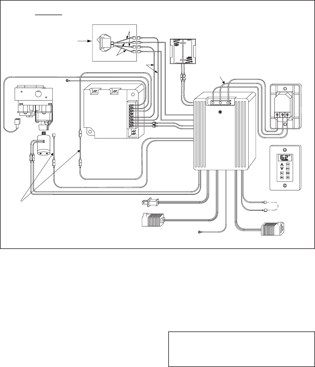
Intellifi re (IPI):
Find these parts packed with WSK-MLT:
• Rocker switch
• Rocker switch bracket
• Strips of Velcro
• Black and white wire pigtails - (2)
• Female ends (not used on IPI applications) - (2)
Slide rocker switch into bracket until it snaps into place.
Attach one pigtail to one side of rocker switch and the other
pigtail to the other side of the rocker switch. Find the two
brown wires from IPI module and attach them to the two
black wires from the rocker switch. Find the two brown
wires from the control box and attach them to the white
wires from the rocker switch. Attach the Velcro to rocker
switch bracket and place rocker switch next to control box.
(Refer to Figure 5).
Proceed to Step 4.
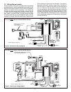
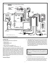
Figure 5. Intellifi re (IPI) Wiring Diagram
For units WITHOUT factory installed Rocker Switch
* May be labeled as “W” or “Y”.
BROWN
WHITE
BLACK
YELLOW
or
WHITE
BLACK
TOGETHER
CONNECTED
FACTORY
FAN THERMOSTAT
YELLOW
YELLOW
FLAME ON
3V DC
GREEN
RED
BROWN
BLACK
GROUND
BROWN
ADAPTER WIRES
BLACK
RED
RED
BLACK
FLAME HIGH/LOW
SOLENOID
FLAME
MODULE
IPI
ORANGE
G
W*
R
8
7
6
5
4
3
2
1
BATTERIES
ORANGE
CONNECTION
FAN
PLUG
AC
BLACK
BLACK
G W* R
REAR VIEW
FRONT VIEW
CONNECTION
AUX
GREEN
PIGTAIL
GROUND
RED
RED
GREEN
ORANGE
VALVE
IPI
(MALE/FEMALE)
RED
RED
(FEMALE/MALE)
BLACK
RED
SWITCH AND WIRE
ASSEMBLY
SUPPLIED
WITH WSK-MLT
Note: The fan rheostat has now been removed from the
circuit and is inoperable. Use the wall switch to change fan
speeds. The fan temperature sensor is still operable and
will turn the fan on and off when the fi replace heats up and
cools down.
5. Remove the screw and knob from the variable regulator
and discard.
6. Unscrew the nut from the regulator and discard.
7. Remove the bag containing a washer and blue and red
plungers from the side of the fl ame control solenoid.
8. Place washer on fl ame control solenoid (see Figure 6).
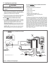
4. If equipped with a fan, plug the fan cord into the power
cord labeled “FAN”. Disconnect the two wires from the
fan thermostat switch on the fi replace. Disconnect the
two yellow wires from each other and connect them to
the fan thermostat switch. Use one of the existing wires
on the thermostat to connect to the proper end on the
male terminated yellow wire.