


Multimedia Traffic Control with IP Multicast (IGMP)
How IGMP Operates
Routing Switch
2
Routing Switch 3
Border
router 1
PIM DM DOMAIN
VLAN 3
V
LA
N
4
Proxy joins
towards Border
router 1
Border
router 2
Routing Switch 1
VLAN 1
VLAN 2
Initial IGMP
join
For 235.1.1.1
V
L
A
N
5
Proxy joins towards Border router 2
PIM SM DOMAIN
Multicast traffic source
(Multicast address
235.1.1.1
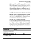
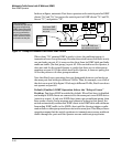
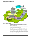
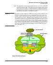
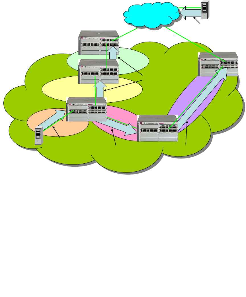
Figure 2-4. IGMP Proxy Example
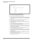
4. Routing Switch 2 then proxies the IGMP join into VLAN 3, which is
connected to Border Router 1.
5. Border Router 1 uses PIM-SM to find and connect to the multicast traffic
for the requested traffic. The traffic is flooded into the PIM-DM network
where it is routed to the original joining host.
6. Additionally, the join was proxied from Routing Switch 3 to Border Router
2. At first, both border routers will flood the traffic into the PIM-DM
domain. However, PIM-DM only forwards multicasts based on the short-
est reverse path back to the source of the traffic as determined by the
unicast routing tables (routing FIB). Only one multicast stream is sent to
the joining host. This configuration provides a redundant link in case the
first link fails.
2-20