


107
4 Summary of the HP/Phoenix BIOS
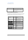
HP/Phoenix BIOS (BIOS version: GJ.07.xx)
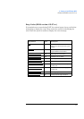
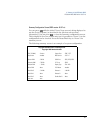
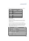
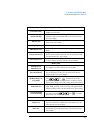
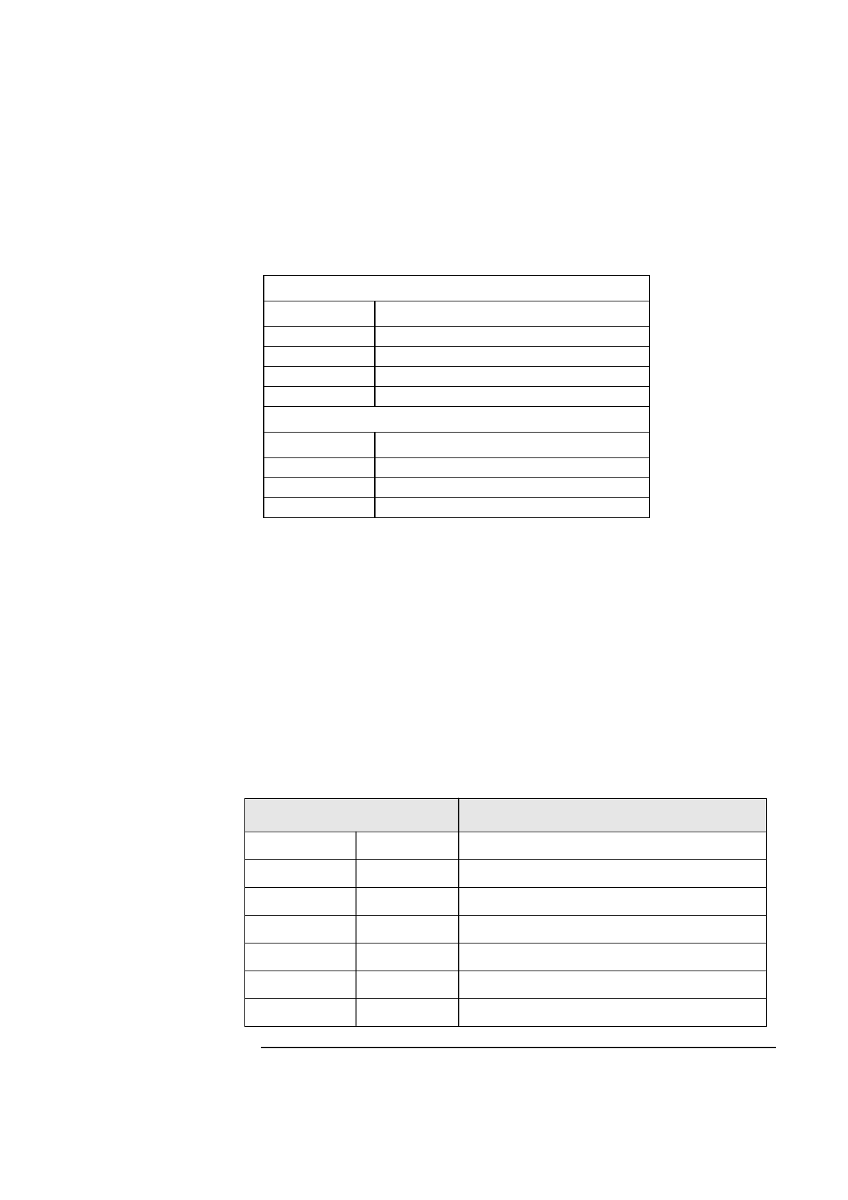
The following table summarizes how the DMA channels are allocated.
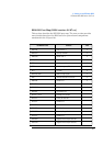
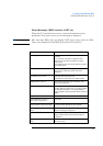
Interrupt Controllers
(BIOS version: GJ.07.xx)
The system has two 8259A compatible interrupt controllers. They are
arranged as a master interrupt controller and a slave that is cascaded
through the master.
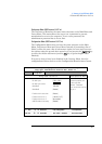
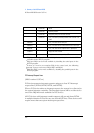
The following table shows how the master and slave controllers are
connected. As the HP Vectra 500 Series incorporates the Plug and Play
mode, some of the IRQ settings indicated in the following table could be
different. This table should be used as a guideline only. The Interrupt
Requests (IRQ) are numbered sequentially, starting with the master
controller, and followed by the slave.
First DMA controller (used for 8-bit transfers)
Channel Function
0 Available
1 Available or ECP mode for parallel port
2 Floppy disk I/O
3 Available or ECP mode for parallel port
Second DMA controller (used for 16-bit transfers)
Channel Function
4 Cascade from first DMA controller
5-6 Available
6-7 Available
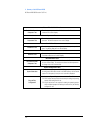
IRQ (Interrupt Vector) Interrupt Request Description
IRQ0(08h) System timer
IRQ1(09h) Keyboard controller
IRQ2(0Ah) Slave IRQ Cascade connection from INTC2 (Interrupt Controller 2)
IRQ8(70h) Real time clock
IRQ9(71h) Available for PCI expansion cards, if not used by ISA boards
IRQ10(72h) Available for PCI expansion cards, if not used by ISA boards
IRQ11(73h) Available for PCI expansion cards, if not used by ISA boards