


2-11
Installing the Switch
Installation Procedures
Installing the Switch
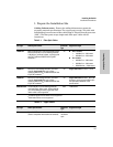
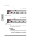
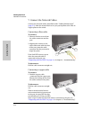
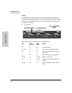
When the self test completes successfully:
•The Power and Fan Status LEDs remain on.
•The Fault and Test LEDs go off.
• The port LEDs (includes the expansion module LEDs) go into their
normal operational mode:
– If the ports are connected to active network devices, the LEDs
behave according to their function, Link or Activity.
– If the ports are not connected to active network devices, the LEDs
will stay off.
If the LED display is different than what is described above, especially if
the Fault and Test LEDs stay on for more than 60 seconds or they start
blinking, the self test has not completed correctly. Refer to chapter 4,
“Troubleshooting” for diagnostic help.
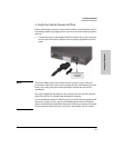
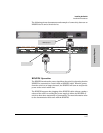
3. After the self test has completed successfully disconnect the power cord
in preparation for mounting the switch.
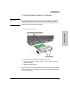
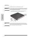
5. Mount the Switch
After the switch passes self test, you are ready to mount the switch in a stable
location. The Series 6400cl Switch devices can be mounted in these ways:
■ in a rack or cabinet
■ on a horizontal surface
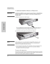
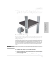
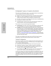
Rack or Cabinet Mounting
The Series 6400cl Switch devices are designed to be mounted in any EIA-
standard 19-inch telco rack or communication equipment cabinet.
WARNING For safe operation, please read the installation precautions on
page 2-4, before mounting a switch.
Equipment
Cabinet
Note
The 12-24 screws supplied with the switch are the correct threading for
standard EIA/TIA open 19-inch racks. If you are installing the switch in an
equipment cabinet such as a server cabinet, use the clips and screws that came
with the cabinet in place of the 12-24 screws that are supplied with the switch.
Complete step 1, and plan which four holes you will be using in the cabinet
and install all four clips. Then proceed to step 2.