


2-17
Installing the Switch
Installation Procedures
Installing the Switch
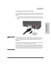
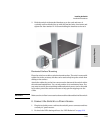
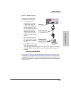
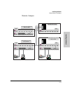
The following picture demonstrates and example of connectivity between an
RPS/EPS device and a Switch device.
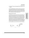
RPS/EPS Operation
The RPS/EPS monitors the power signal from the switch by detecting that the
RPS/EPS is connected to a switch with an RPS/EPS cable. When the power
from the switch is no longer detected, the RPS/EPS will turn on and provide
power to the switch within 1ms.
The RPS/EPS supports hot plugging of the RPS/EPS cable without causing a
reboot of the switch or causing the power supply in either the RPS/EPS or
switch to shut down temporarily or permanently. For more information refer
to the documentation that came with the RPS/EPS.
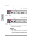
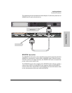
Device Connected
Power Sta tus
R1 R2 R3 R4 R5 R6 E1
Device
Connected
Pow er
Status
E2
RPS 1 RPS 2 RPS 3 RPS 4 RPS 5 RPS 6 EPS 1 EPS 2
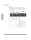
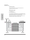
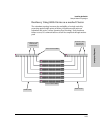
EPS Power: 50V 370W total for PoE applications. Power is shared when both ports are used.RPS Power: 12V backup to one connected device. Lowest-numbered port has priority.
Line: 50/60 Hz.
100-240 V~ 9.1A (9,1A)
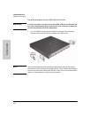
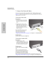
Switch 6400cl device,
RPS input port
RPS output port