


Removal and replacement procedures 68
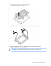
8.
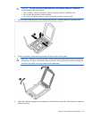
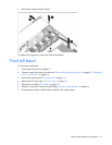
Remove the three T-10 Torx screws, and then detach the front bezel.
To replace the component, reverse the removal procedure.
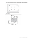
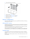
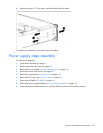
Power supply cage assembly
To remove the component:
1. Power down the server (on page 27).
2. Access the product rear panel (on page 29).
3. Remove all power supplies ("Hot-plug power supply" on page 32).
4. Remove the server from the rack (on page 28).
5. Remove the access panel ("Access panel" on page 34).
6. Remove the PCI riser cage ("PCI riser cage" on page 44).
7. Remove the air baffle ("Air baffle" on page 49).
8. Remove the power supply backplane ("Power supply backplane" on page 38).
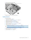
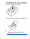
9. Loosen the system board thumbscrews, and then slide the system board assembly forward.