


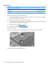
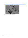
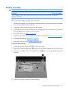
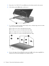
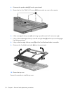

5. Remove the six Torx T8M2.5×9.0 screws (1) that secure the display assembly to the computer.
6. Lift the display assembly (2) straight up and remove it.
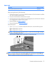
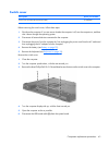
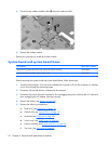
7.
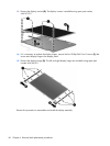
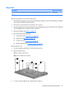
If it is necessary to replace the display bezel, display inverter, or display hinges, remove the rubber
screw covers and screws listed below.
(1) Four rubber screw covers on the display bezel top edge.
(2) Two rubber screw covers on the display bezel bottom edge.
(3) Four Torx T8M2.5×5.0 screws on the display bezel top edge.
(4) Two Torx T8M2.5×7.0 screws on the display bezel bottom edge.
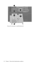
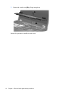
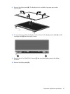
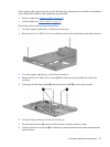
8. Flex the inside edges of the top (1) edge, left and right sides (2), and the bottom edge (3) of the
display bezel until the bezel disengages from the display enclosure.
46 Chapter 4 Removal and replacement procedures