


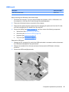
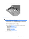
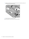
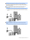
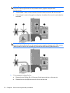
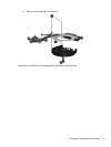
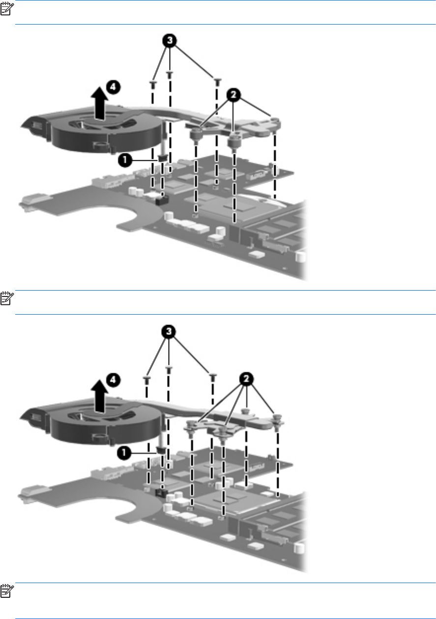
5. Remove the fan and heat sink (4).
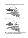
NOTE: The following illustration shows the fan and heat sink being removed from a computer
model equipped with an AMD processor and a graphics subsystem with discrete memory.
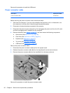
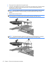
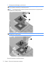
NOTE: The following illustration shows the fan and heat sink being removed from a computer
model equipped with an Intel processor and a graphics subsystem with discrete memory.
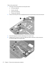
NOTE: Steps 6 through 8 apply only to computer models equipped with a graphics subsystem
with UMA memory. See steps 2 through 5 for fan and heat sink removal information for
computer models equipped with a graphics subsystem with discrete memory.
Component replacement procedures 67