


Display assembly subcomponents
NOTE: The display assembly is spared at the subcomponent level only. For more display assembly
spare part information, see the individual removal subsections.
To access the display assembly subcomponents, follow these steps:
1. Turn off the computer. If you are unsure whether the computer is off or in Hibernation, turn the
computer on, and then shut it down through the operating system.
2. Disconnect the power from the computer by unplugging the power cord from the computer.
3. Disconnect all external devices from the computer.
4.
Remove the battery (see
Battery on page 45), and then remove the following components:
a. Service cover (see
Service cover on page 47)
b. Hard drive (see
Hard drive on page 48)
c. Optical drive (see
Hard drive on page 48)
d. WLAN module (see
WLAN module on page 51)
e. WWAN module (see
WWAN module on page 53)
f. Fan (see
Fan on page 57)
g. Keyboard (see
Keyboard on page 58)
h. Base enclosure (see
Base enclosure on page 63)
i.
System board (see
System board on page 75)
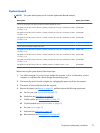
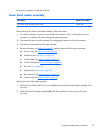
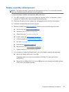
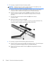
1. If it is necessary to replace the display bezel or any of the display assembly subcomponents:
a. Remove the display bezel screw covers (1).
The display bezel screw covers are available in the Rubber Kit, spare part number
693355-001.
b.
Remove the two Phillips PM2.0×4.2 screws (2) that secure the display bezel and the display
clutch cover to the display assembly.
Component replacement procedures
83