


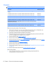

Processor
NOTE: The processor spare part kit includes replacement thermal material.
Description Spare part number
Next Generation Intel® Core™ processors, (support Intel Turbo Boost Technology) (includes replacement thermal
material):
i7-3610QM, 2.30 GHz (Turbo up to 3.30 GHz), 1600 MHz, 6 MB L3 Cache, 8 threads, 45W 680646-001
i7-3720QM, 2.60 GHz (Turbo up to 3.60 GHz), 1600 MHz, 6 MB L3 Cache, 8 threads, 45W 681283-001
i7-3820QM, 2.70 GHz (Turbo up to 3.70 GHz), 1600 MHz, 8 MB L3 Cache, 8 threads, 45W 681284-001
i7-3520M, 2.90 GHz (Turbo up to 3.60 GHz), 1600 MHz, 4 MB L3 Cache, 4 threads, 35W 681954-001
i7-3920XM, 2.90 GHz (Turbo up to 3.80 GHz), 1600 MHz, 8 MB L3 Cache, 8 threads, 55W 691351-001
Next Generation Intel® Core™ i5 processors, (support Intel Turbo Boost Technology) (includes
replacement thermal material):
i5-3360M, 2.80 GHz (Turbo up to 3.50 GHz), 1600 MHz, 3 MB L3 Cache, 4 threads, 35W 681953-001
i5-3320M, 2.60 GHz (Turbo up to 3.30 GHz), 1600 MHz, 3 MB L3 Cache, 4 threads, 35W 681952-001
Before removing the processor, follow these steps:
1. Shut down the computer. If you are unsure whether the computer is off or in Hibernation, turn
the computer on, and then shut it down through the operating system.
2. Disconnect all external devices connected to the computer.
3. Disconnect the power from the computer by first unplugging the power cord from the AC outlet
and then unplugging the AC adapter from the computer.
4. Remove the battery (see
Battery on page 51)
5. Remove the service access cover (see
Service access cover on page 52).
6. Remove the optical drive (see
Optical drive on page 63) or upgrade bay hard drive (see Upgrade
bay hard drive on page 66).
7. Remove the keyboard (see
Keyboard on page 71).
8. Remove the top cover (see
Top cover on page 83).
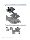
9. Remove the fan/graphics board heat sink assembly (see
Fan/graphics board heat sink assembly
on page 75).
10. Remove the processor heat sink (see
Processor heat sink on page 110).
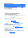
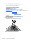
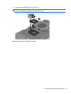
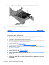
Remove the processor:
1. Use a flat-bladed screwdriver to turn the processor locking screw (1) one-half turn
counterclockwise, until you hear a click.
112 Chapter 4 Removal and replacement procedures