g. USB board (see USB board on page 90).
h. System board (see
System board on page 92).
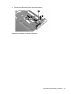
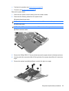
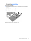
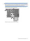
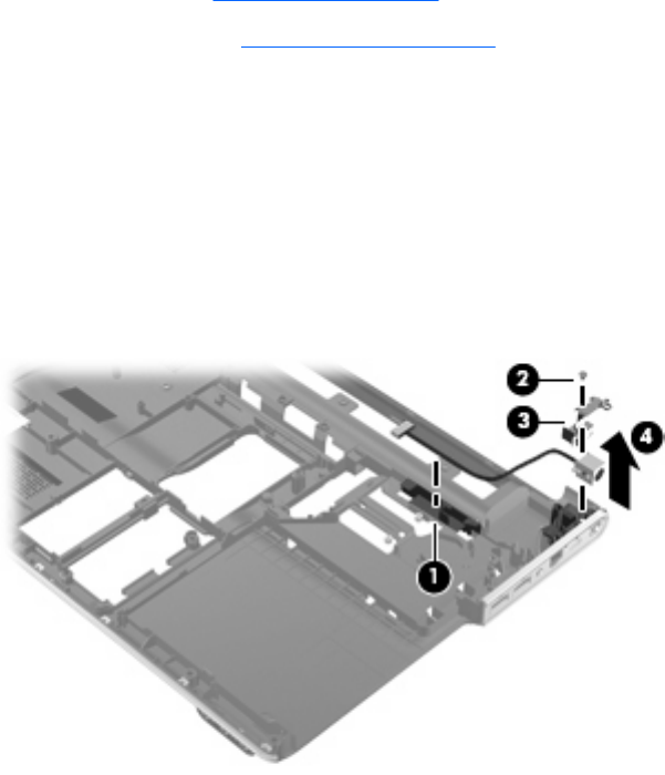
Remove the power connector cable:
1. Remove the power connector cable (1) from the clips and routing channel built into the base
enclosure.
2. Remove the Phillips PM2.5×7.0 screw (2) that secures the power connector and bracket to the
base enclosure.
3. Remove the power connector bracket (3).
4. Remove the power connector cable (4).
Reverse this procedure to install the power connector cable.
Component replacement procedures 97


