


Fan/heat sink assembly
NOTE: All fan/heat sink assembly spare kits include replacement thermal material.
Description Spare part number
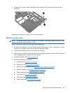
For use only with computer models equipped with AMD processors and graphics subsystems with
discrete memory
493001-001
For use only with computer models equipped with AMD processors and graphics subsystems with
UMA memory
491572-001
For use only with computer models equipped with Intel processors and graphics subsystems with
discrete memory
486799-001
For use only with computer models equipped with Intel processors and graphics subsystems with
UMA memory
492314-001
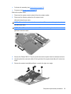
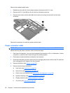
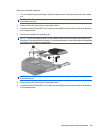
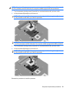
NOTE: To properly ventilate the computer, allow at least a 7.6-cm (3-inch) clearance on the right side
and rear panel of the computer. The computer uses an electric fan for ventilation. The fan is controlled
by a temperature sensor and is designed to turn on automatically when high temperature conditions
exist. These conditions are affected by high external temperatures, system power consumption, power
management/battery conservation configurations, battery fast charging, and software applications.
Exhaust air is displaced through the ventilation grill located on the left side of the computer.
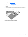
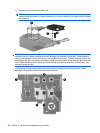
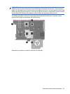
Before removing the fan/heat sink assembly, follow these steps:
1. Shut down the computer. If you are unsure whether the computer is off or in Hibernation, turn the
computer on, and then shut it down through the operating system.
2. Disconnect all external devices connected to the computer.
3. Disconnect the power from the computer by first unplugging the power cord from the AC outlet and
then unplugging the AC adapter from the computer.
4. Remove the battery (see
Battery on page 52).
5. Remove the following components:
a. Hard drive (see
Hard drive on page 62).
b. Optical drive (see
Optical drive on page 55).
c. Switch cover and keyboard (see
Switch cover and keyboard on page 69).
d. Speaker assembly (see
Speaker assembly on page 74).
e. Display assembly (see
Display assembly on page 76).
f. Top cover (see
Top cover on page 84).
g. USB board (see
USB board on page 90).
h. System board (see
System board on page 92).
98 Chapter 4 Removal and replacement procedures