


product description
audio 2
camera 2
chipset 1
diskette drive 2
display panel 1
docking support 3
Ethernet 2
external media cards 2
graphics 1
hard drives 1
keyboard 3
memory module 1
microphone 2
modem module 2
operating system 3
optical drives 2
pointing devices 3
ports 2
power requirements 3
processors 1
product name 1
security 3
serviceability 3
wireless 2
product name 1
R
rear component 14
recovery discs 113
recovery partition, deleting 116
recovery, system 115
remote control, spare part
numbers 24, 25, 26
removal/replacement
preliminaries 28
procedures 34
restore points 112
RF input adapter cable, spare part
number 24, 25
right-side components 13
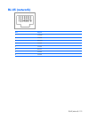
RJ-45 jack
location 12
pin assignments 119
RTC battery
removal 45
spare part number 19, 26,
45
Rubber Kit, spare part
number 19, 25, 35
S
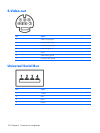
S-Video-out jack
location 12
pin assignments 120
Screw Kit
contents 92
spare part number 24, 25
screw listing 92
secondary hard drive self test 82
security cable slot 12
Security menu 82
security, product description 3
selecting in the Setup Utility 80
serial number 16, 34
service considerations 28
serviceability, product
description 3
Setup Utility
changing the language 79
Diagnostics menu 82
displaying system
information 80
Main menu 81
navigating 80
overview 79
Security menu 82
selecting 80
starting 79
System Configuration menu 82
using advanced features 81
software
reinstalling 114
updating 116
speaker assembly
removal 51
spare part number 18, 25,
51
speakers 7
specifications
computer 83
display 84
DVD±RW and CD-RW Combo
Drive 86
hard drive 85
I/O addresses 89
interrupts 88
memory map 91
optical drive 86
system DMA 87
static-shielding materials 32
stop button 8
switch cover
removal 49
spare part number 18, 26,
49
system board
removal 68
spare part number 18, 27,
68
System Configuration menu 82
system DMA 87
system information 80, 81
system memory map 91
T
thermal material, replacement 75
tools required 28
top components 6
top cover
removal 61
spare part number 18, 26,
61
top cover trim
removal 63
spare part number 18, 25,
63
TouchPad 10
TouchPad buttons 10
TouchPad light 10
TouchPad on/off button 10
TouchPad scroll zone 10
transporting guidelines 31
TV tuner antenna, spare part
number 24, 26
TV tuner, spare part number 24,
25
U
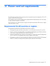
Universal Serial Bus (USB) port
locations 12, 13
pin assignments 120
unknown password 33
USB digital drive, spare part
number 24, 25
USB/power connector board
removal 67
spare part number 19, 26,
67
USB/power connector board cable,
illustrated 22
132 Index