


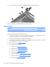
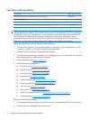

Fan/heat sink assembly
Description Spare part number
Fan/heat sink assembly (includes replacement thermal material) 446521-001
Processor brackets
For use only with computer models equipped with T7250, T5550, T5450, and T5250 processors
450371-001
For use only with computer models equipped with T7700 and T7500 processors 450370-001
NOTE: To properly ventilate the computer, allow at least a 7.6-cm (3-inch) clearance on the right side
and rear panel of the computer. The computer uses an electric fan for ventilation. The fan is controlled by
a temperature sensor and is designed to turn on automatically when high temperature conditions exist.
These conditions are affected by high external temperatures, system power consumption, power
management/battery conservation configurations, battery fast charging, and software requirements.
Exhaust air is displaced through the ventilation grill located on the left side of the computer.
Before removing the fan/heat sink assembly, follow these steps:
1.
Shut down the computer. If you are unsure whether the computer is off or in Hibernation, turn the
computer on, and then shut it down through the operating system.
2.
Disconnect all external devices connected to the computer.
3.
Disconnect the power from the computer by first unplugging the power cord from the AC outlet and
then unplugging the AC adapter from the computer.
4.
Remove the battery (see
Battery on page 36).
5.
Remove the following components:
a.
Hard drives (see
Hard drives on page 41)
b.
Optical drive (see
Optical drive on page 47)
c.
Switch cover (see
Switch cover on page 49)
d.
Keyboard (see
Keyboard on page 53)
e.
Speaker assembly (see
Speaker assembly on page 51)
f.
Display assembly (see
Display assembly on page 55)
g.
Top cover (see
Top cover on page 61)
h.
Audio board (see
Audio board on page 71)
i.
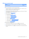
USB/power connector board (see
USB/power connector board on page 67)
j.
System board (see
System board on page 68)
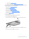
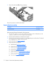
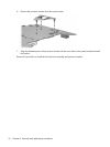
Remove the fan/heat sink assembly:
1.
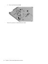
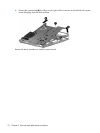
Turn the system board upside down with the expansion port 3 and external monitor port toward you.
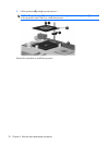
2. Disconnect the fan cable (1) from the system board.
74 Chapter 4 Removal and replacement procedures