


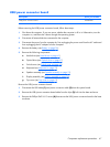
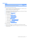

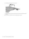
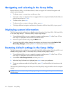
3. Loosen the three Phillips PM2.5×5.0 screws (2) and the Phillips PM2.5×4.0 screw (3) that secure
the fan/heat sink assembly to the system board.
4. Remove the fan/heat sink assembly (4).
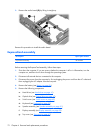
NOTE: Due to the adhesive quality of the thermal material located between the fan/heat sink
assembly and system board components, it may be necessary to move the fan/heat sink assembly
from side to side to detach the assembly.
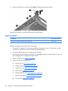
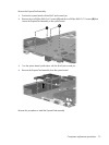
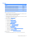
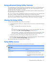
NOTE: The thermal material must be thoroughly cleaned from the surfaces of the fan/heat sink
assembly (1) and (2), the Northbridge chip (3), and the processor (4) each time the fan/heat sink
assembly is removed. Thermal material must be installed on all surfaces before the fan/heat sink
assembly is reinstalled. Replacement thermal material is included with all fan/heat sink assembly,
system board, and processor spare part kits.
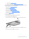
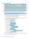
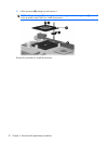
5.
If it is necessary to replace the processor bracket, turn the system board upside down, with the
expansion port 3 and external monitor port toward you.
Component replacement procedures 75