


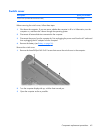
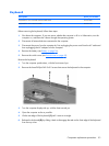
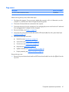

9.
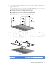
If it is necessary to replace the display bezel or any of the display assembly internal components,
remove the following:
(1) Four rubber screw covers on the display bezel top edge. The display rubber screw covers are
included in the Display Screw Kit, spare part number 431399-001.
(2) Two rubber screw covers on the display bezel bottom edge.
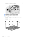
(3) Two Phillips PM2.5×8.0 screws on the display bezel bottom edge.
(4) Four Phillips PM2.5×6.0 screws on the display bezel top edge.
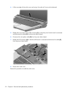
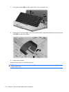
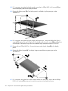
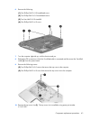
10. Flex the inside edges of the left and right sides (1) and the top and bottom sides (2) of the display
bezel until the bezel disengages from the display enclosure.
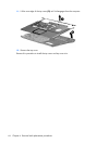
11. Remove the display bezel (3). Display bezels are available using spare part numbers 446483-001
(for use with computer models equipped with a camera and microphones) and 433281-001 (for use
with computer models equipped with microphones).
NOTE: See Camera module on page 37 for camera module replacement instructions. See Display
inverter on page 39 for display inverter replacement instructions.
Component replacement procedures 57