


6-2 Program Simulation Copyright © 2000 Hewlett-Packard Co.
Ski IA-64 Simulator Reference Manual 1.0L
6.3.1 System-Mode IA-64 Programs
A system-mode IA-64 program “sees” a more complete simulated environment: writeable registers are initialized to zero,
page and TLB faults are simulated and cause a transfer to the interruption vector table (IVT), privileged instructions can
be executed, privileged registers can be accessed, and so on. A tricky issue for system-mode simulation is handling I/O
because there are no real I/O devices to simulate! Instead, Ski provides a special interface using BREAK instructions to
implement Simulator SystemCalls (SSC’s), which provide access to the console, keyboard, SCSI disk and Ethernet
devices. A system-mode IA-64 program can’t access the underlying operating system; it “thinks” it’s running on a real IA-
64 computer.
A system-mode IA-64 program must provide interruption handlers. The program must create a valid Interruption Vector
Table (IVT) and set the Interruption Vector Address (IVA) accordingly. You can test your interruption code by creating
code that generates conditions corresponding to internal faults, traps, and interrupts, such as divide-by-zero and page-not-
present. To test code for external interrupts, use the inter-processor interruption mechanism, as defined by the IA-64 archi-
tecture manual. Example assembly code for this is shown in Figure 6-1. Timer interruptions can be simulated using the
Simulator System Call mechanism.
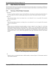
6.3.2 System-Mode IA-32 Programs
Ski does not support IA-32 programs running in system-mode.
6.3.3 System-Mode TLB Simulation
The simulator provides facilities for modeling the TLB’s (Translation Lookaside Buffers) for system-mode programs.
6.3.3.1 Summary of TLB Display Commands
sit
sdt
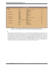
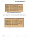
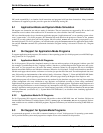
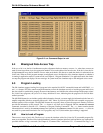
When a system-mode IA-64 program is loaded, these commands display information from the Instruction Translation
Lookaside Buffer (ITLB) and Data Translation Lookaside Buffer (DTLB), respectively. The simulator displays the
entire selected TLB (Translation Registers and the Translation Cache) on the screen, as shown in Figure 6-2.
The “V” and “RID” columns represent the V (valid) bit and Region Identifier, respectively, for each TLB entry. The
“Virtual Page” and “Physical Page” columns show the actual address translation handled by each TLB entry.
The “PgSz”, “ED”, “AR”, “PL”, “D”, “A”, “MA”, and “P” columns represent the Page Size, Exception Deferral, Access
Rights, Privilege Level, Dirty Bit, Accessed Bit, Memory Attribute, and Present fields, respectively, for each TLB
entry. Finally, the “KEY” column represents the Protection Key for each TLB entry. A blank line separates the
Translation Registers (TR’s) from the Translation Cache (TC). The number of TR’s and the size of the TC is
implementation-dependent. Current versions of Ski provide 16 TR’s and 128 entries for the TC but this may change.
If the precise value is important, check the release notes.
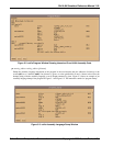
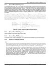
Figure 6-1. Example Code to Simulate an External Interrupt
ssm 0x6000 // Set psr.i and psr.ic to 1
mov cr.lid=r0 // For processor 0
movl r4=0xfee00000 // Interrupt block base for proc 0
mov r5=0x10 // Interrupt vector 16
st8 [r4]=r5 // Code branches to iva+0x3000 (the external
// interrupt handler). irr0{16} is set to 1,
// ivr = 0x10