


4-2 www.hp.com Technical Reference Guide
System Support
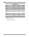
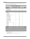
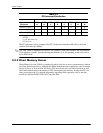
Table 4-1 shows the standard configuration of device numbers and IDSEL connections for
components and slots residing on a PCI 2.3 bus.
NOTES:
[1] Function not used in these systems.
[2] USB 1.1 controllers in 6+6 configuration. 8+4 configuration will have USB 1.1 controller #6 use Function 26, Device 2.
[3] SFF and CMT form factors only.
[4] CMT form factor only
[5] Function is only visible in IDE mode (not visible in AHCI orRAID SATA emulation mode).
Table 4-1
PCI Component Configuration Access
PCI Component Notes Function # Device #
PCI Bus
#
IDSEL
Wired to:
Q45 GMCH:
Host/DMI Bridge
Host/PCI Expr. Bridge
Integrated Graphics Cntlr.
0
0
0
28
1
2
0
0
0
--
PCI Express x16 graphics slot 0 0 1 --
82801 ICH10
PCI Bridge
LPC Bridge
SATA Controller #1
SMBus Controller
SATA/eSATA Controller #2
Thermal System
USB 1.1 Controller #1
USB 1.1 Controller #2
USB 1.1 Controller #3
USB 1.1 Controller #4
USB 1.1 Controller #5
USB 1.1 Controller #6
USB 2.0 Controller #1
USB 2.0 Controller #2
GbE NIC
Intel HD audio controller
PCIe port 1
PCIe port 2
PCIe port 3
PCIe port 4
PCIe port 5
PCIe port 6
[5]
[3]
[1]
[1]
[1]
0
0
2
3
5
6
0
1
2
0
1
3 [2]
7
7
0
0
0
1
2
3
4
5
30
31
31
31
31
31
29
29
29
26
26
29 [2]
29
26
25
27
28
28
28
28
28
28
0
0
0
0
0
0
0
0
0
0
0
0
0
0
0
0
0
0
0
0
0
--
PCI 2.3 slot 1 [3] 0 4 7 AD20
PCI 2.3 slot 2 [3] 0 11 7 AD25
PCI 2.3 slot 3 [4] 0 10 7 AD27
PCIe x1 slot 1 [3] 0 0 32
PCIe x1 slot 2 [3] 0 0 48