


Technical Reference Guide www.hp.com 5-5
Input/Output Interfaces
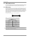
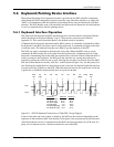
The SFF and CMT form factors use a standard 34-pin connector for diskette drives (refer to
Figure 5-3 and Table 5-3 for the pinout). Drive power is supplied through a separate connector.
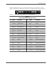
Figure 5-3. 34-Pin Diskette Drive Connector (P10 on system board).
Table 5-3.
34-Pin Diskette Drive Connector Pinout
Pin Signal Description Pin Signal Description
1 GND Ground 18 DIR- Drive head direction control
2LOW DEN-Low density select 19 GND Ground
3 --- (KEY) 20 STEP- Drive head track step cntrl.
4 MEDIA ID- Media identification 21 GND Ground
5 GND Ground 22 WR DATA- Write data
6DRV 4 SEL-Drive 4 select 23 GND Ground
7GND Ground 24 WR ENABLE-Enable for WR DATA-
8 INDEX- Media index is detected 25 GND Ground
9 GND Ground 26 TRK 00- Heads at track 00 indicator
10 MTR 1 ON- Activates drive motor 27 GND Ground
11 GND Ground 28 WR PRTK- Media write protect status
12 D RV 2 SE L- Drive 2 se le ct 29 G ND Grou nd
13 GND Ground 30 RD DATA- Data and clock read off disk
14 DRV 1 SE L- D rive 1 se l ec t 31 G N D G ro u nd
15 GND Ground 32 SIDE SEL- Head select (side 0 or 1)
16 MTR 2 ON- Activates drive motor 33 GND Ground
17 GND Ground 34 DSK CHG- Drive door opened indicator
1
2 4
5
6
7
8
9
10
11
12
13
14
15
16
17
18
19
20
21
22
23
24
25
26
27
28
29
30
31
32
33
34