


Technical Reference Guide www.hp.com 7-5
Power and Signal Distribution
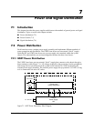
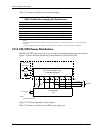
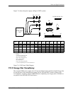
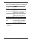
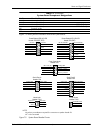
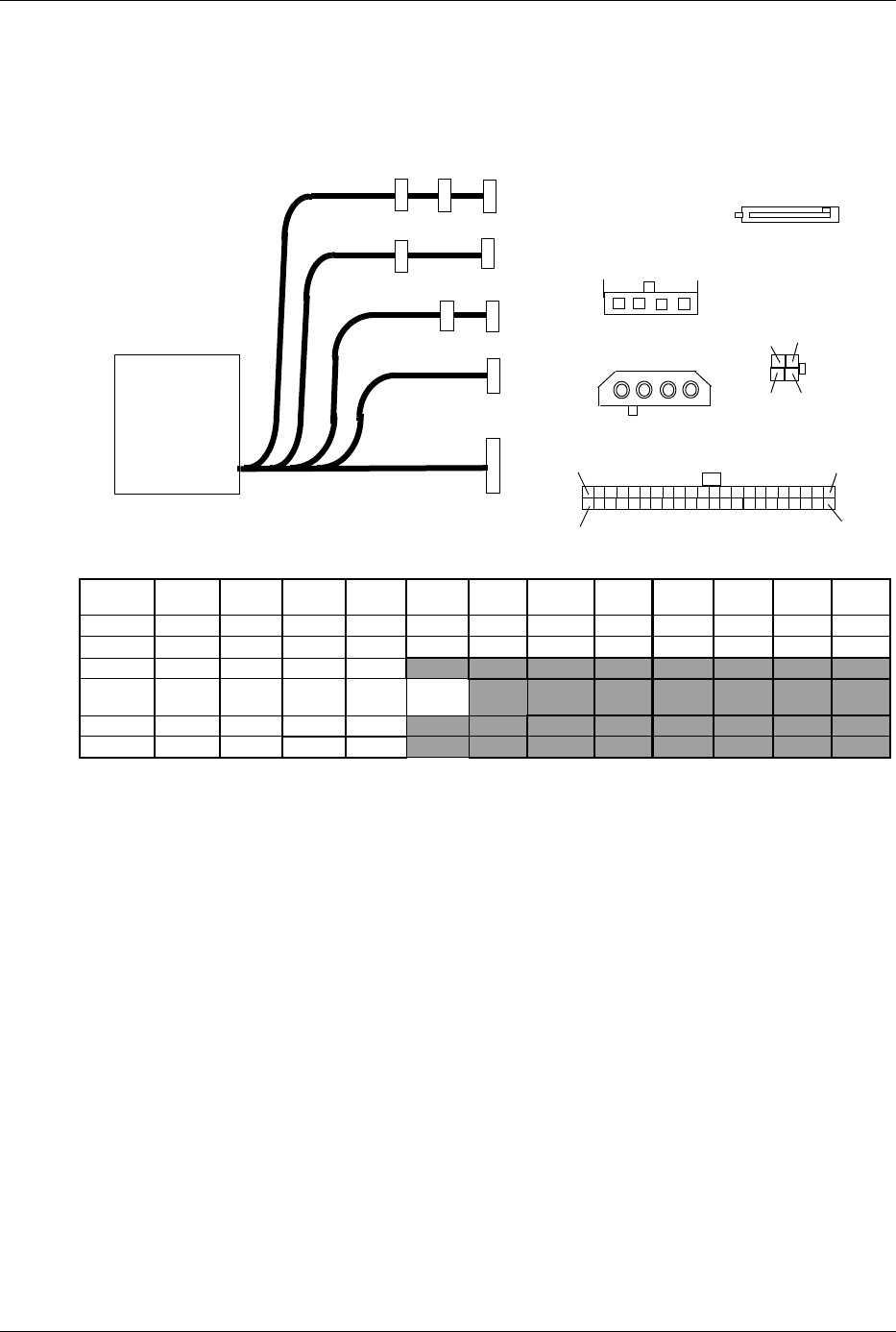
Figure 7-4 shows the power supply cabling for CMT systems.
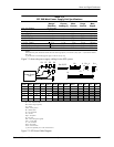
NOTES:
Connectors not shown to scale.
All + and - values are VDC.
RTN = Return (signal ground)
GND = Power ground
RS = Remote sense
POK = Power ok (power good)
[1] This row represents pins 13–24 of connector P1.
Figure 7-4. CMT Power Cable Diagram
7.2.3 Energy Star Compliancy
The standard USDT power supply unit is 87 percent efficient and compliant with the Energy Star
4.0 specification. The standard power supply unit for SFF and CMT systems is Energy Star
3.0-compliant. An Energy Star 4.0 (80Plus Bronze-compliant) power supply unit is available as
an option for the SFF and CMT form factors.
Conn Pin 1 Pin 2 Pin 3 Pin 4 Pin 5 Pin 6 Pin 7 Pin 8 Pin 9
Pin
10
Pin
11
Pin
12
P1 +3.3 +3.3 RTN +5 RTN +5 RTN POK 5 aux +12 +12 +3.3
P1 [1] +3.3 -12 RTN PS On RTN RTN RTN PSDet +5 +5 +5 RTN
P3 RTN RTN VccP VccP
P4, 5, 9,
10, 11
+3.3 RTN +5.08 RTN +12
P6 +12 RTN RTN +5
P8 +5 RTN RTN +12
Power Supply
Unit
P1
P5
P1
13
1
12
P4, P5, P9, P10, P11
24
12
3
4
1
23
4
5
1
2
34
P8
P3
P6
P4
P3
P6
1
3
2
4
P10
P9
P11
P8