


Technical Reference Guide www.hp.com 7-3
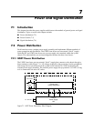
Power and Signal Distribution
NOTES:
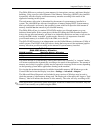
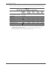
Total continuous power should not exceed 240 watts. Total surge power (<10 seconds w/duty cycle < 5 %) should not exceed
260 watts.
[1] The minimum current loading figures apply to a PS On start up only.
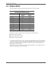
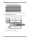
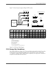
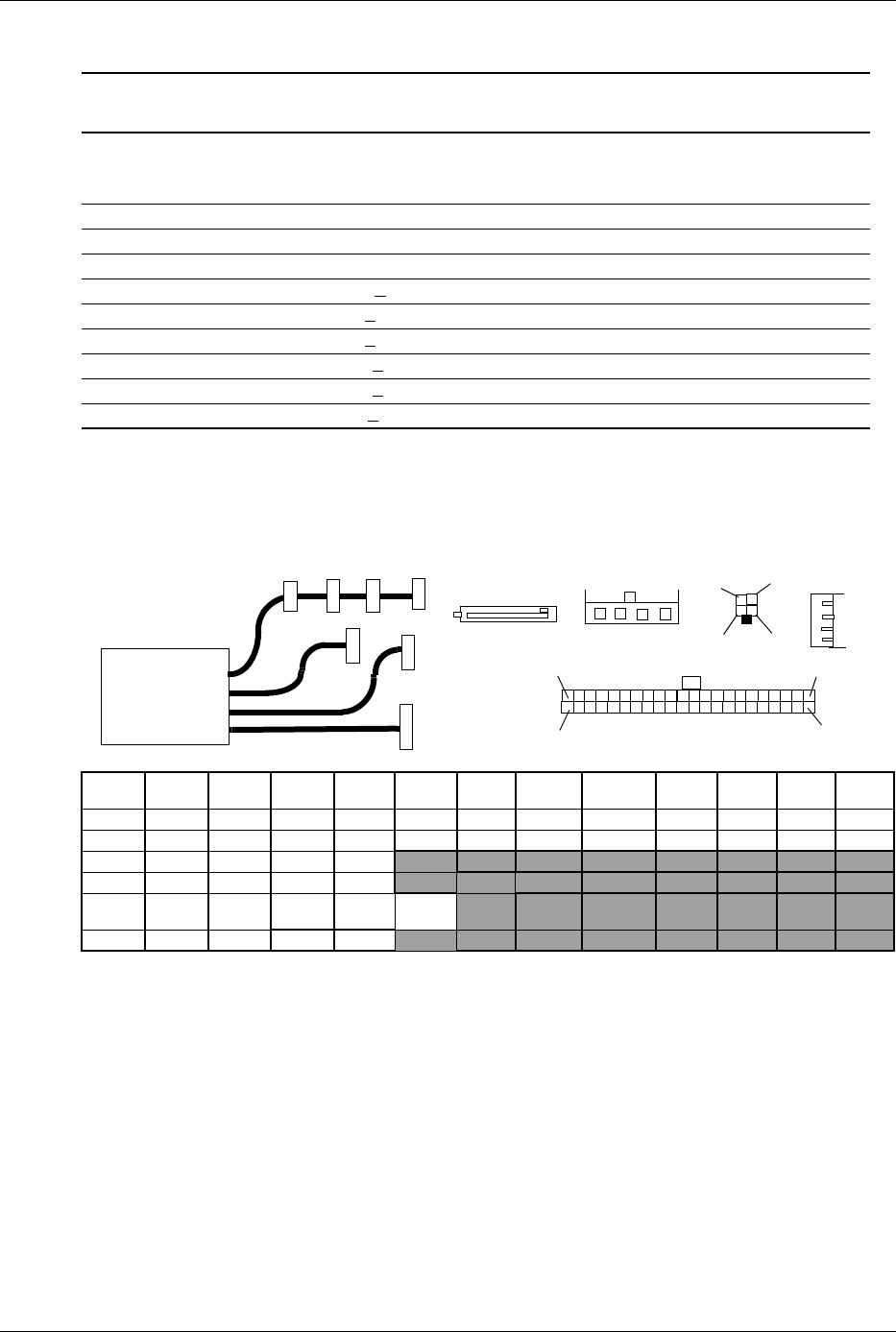
Figure 7-3 shows the power supply cabling for the SFF system.
All + and - values are VDC.
RTN = Return (signal ground)
sns = sense
GND = Power ground
RS = Remote sense
FC = Fan command
FO = Fan off
FSpd = Fan speed
FS = Fan Sink
POK = Power OK (power good)
VccP = +12 for CPU
nc = not connected
Ftach = Fan speed
Fcmd = Fan command
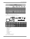
[1] This row represents pins 13–24 of connector P1
Figure 7-3. SFF Power Cable Diagram
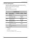
Table 7-2.
SFF 240-Watt Power Supply Unit Specifications
Range/
Tolerance
Min.
Current
Loading [1]
Max.
Current
Surge
Current
Max.
Ripple
Input Line Voltage 90–264 VAC -- -- -- --
Line Frequency 47–63 Hz -- -- -- --
Input (AC) Current -- -- 5.0 A -- --
+3.3 VDC Output +
4% 0.1 A 15.0 A 15.0 A 50 mV
+5.08 VDC Output +
3.3 % 0.3 A 17.0 A 17.0 A 50 mV
+5.08 AUX Output +
3.3 % 0.0 A 3.0 A 3.5 A 50 mV
+12 VDC Output + 5 % 0.1 A 7.5 A 9.0 A 120 mV
+12 VDC Output (Vcpu) +
5 % 0.1 A 11.0 A 14.5 A 120 mv
--12 VDC Output +
10 % 0.0 A 0.15 A 0.15 A 200 mV
Conn Pin 1 Pin 2 Pin 3 Pin 4 Pin 5 Pin 6 Pin 7 Pin 8 Pin 9
Pin
10
Pin
11
Pin
12
P1 +3.3 +3.3 RTN +5 RTN +5 RTN POK 5AUX +12 +12 3.3
P1 [1] +3.3 -12 RTN PS On RTN RTN RTN PS Det +5 +5 +5 RTN
P2 +5 RTN RTN +12
P3 RTN RTN VccP VccP
P4, 5,
7
+3.3 RTN +5 RTN +12
P11 GND nc Ftach Fcmd
Power Supply
Unit
P1
P3
P2
P4
P5
P7
P1
13
1
12
P4, P5, P7
24
1
2
3
4
5
1
2
34
P2
P3
1
2
3
4
P11
1
2
3
4
P11