


7-2 www.hp.com Technical Reference Guide
Power and Signal Distribution
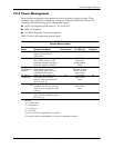
Table 7-1 lists the specifications of the external supply.
NOTES:
Total continuous power should not exceed 135 watts. Total surge power (<10 seconds w/duty cycle < 5 %) should not exceed
170 watts.
[1] Using 100 VAC input. The output voltage is allowed to drop to a minimum of 15 VDC during the transient period.
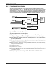
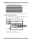
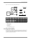
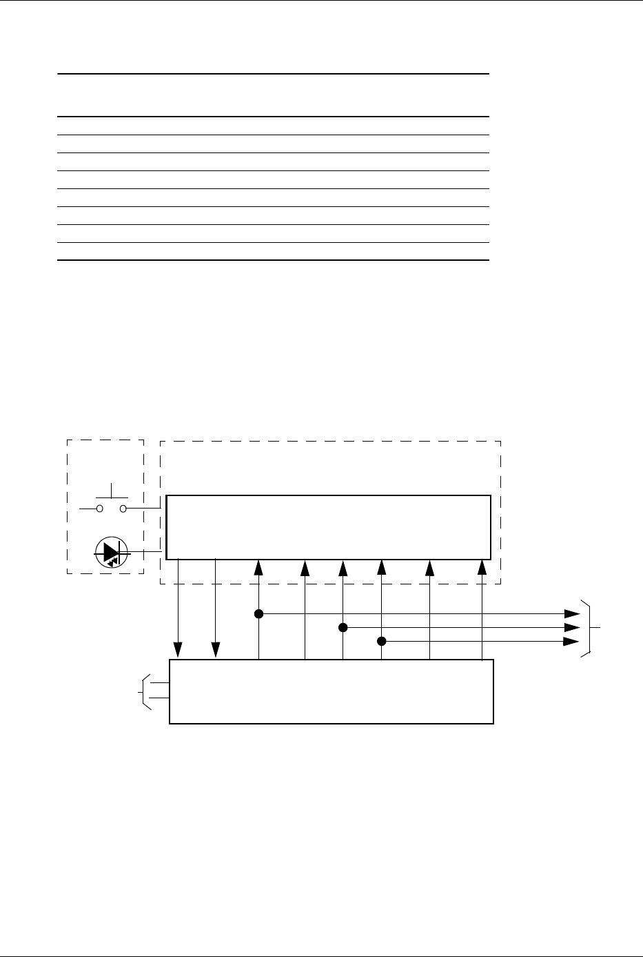
7.2.2 SFF/CMT Power Distribution
The SFF and CMT form factors use a power supply unit contained within the system chassis.
Figure 7-2 shows the block diagram for power generation in the SFF and CMT.
Figure 7-2. SFF Power Generation, Block Diagram
Table 7-2 lists the specifications of the SFF power supply unit.
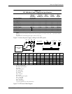
Table 7-1.
USDT 135-Watt Power Supply Unit Specifications
Parameter
Input Line Voltage Range 90–265 VAC
Line Frequency 47–63 Hz
Input Current, Maximum load @ 90 VAC 2.4 A
Output Voltage 19.5 VDC
Output Current, nominal load 3.5 A
Output Current, maximum load 6.9 A
Output Current, peak load (300 ms max) [1] 9.0 A
System Board
Power Supply
Power On
CPU, slots, Chipsets, Logic,
Front Bezel
& Voltage Regulators
Unit
Fan
PS On
+5 VDC
+12 VccP
Power Button
Spd [1]
+12 VDC
-12 VDC
+3.3 VDC
Drives
+3.3 VDC
+5 VDC
+12 VDC
90 - 264 VAC
NOTE:
[1] Not present on CMT.
5 AUX