


1-7
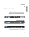
Introducing the Switch
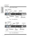
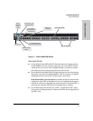
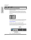
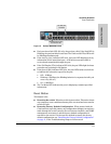
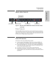
Front of the Switch
Introducing the Switch
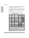
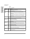
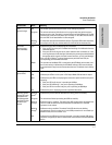
Test
(green/orange)
Off The normal operational state; the switch is not undergoing self test.
On green The switch self test and initialization are in progress after the switch has been
power cycled or reset. The switch is not operational until this LED goes off. The Self
Test LED also comes on briefly when you “hot swap” a mini-GBIC into the switch;
the mini-GBIC is self tested when it is hot swapped.
Blinking
orange
1
A component of the switch has failed its self test. The status LED for that component,
for example an RJ-45 port, and the switch Fault LED will blink simultaneously.
Port LEDs
(green/orange –
Link and Mode)
Link Indicates the port LEDs are displaying link information:
• if the port LED is on, the port is enabled and receiving a link indication from the
connected device.
• if the port LED is off, the port has no active network cable connected, or is not
receiving link beat or sufficient light. Otherwise, the port may have been disabled
through the switch console, the web browser interface, or ProCurve Manager.
if the port LED is Blinking
1
(orange) simultaneously with the Fault LED, the
corresponding port has failed its self test.
Mode The operation of the Mode LED is controlled by the LED Mode select button, and
the current setting is indicated by the LED Mode indicator LEDs near the button.
Press the button to step from one view mode to the next. The default view is Activity
(Act).
LED Mode View
(green LEDs)
Act Indicates the port LEDs are displaying network activity information.
FDx Indicates port LEDs are lit for ports in Full Duplex Mode. Off indicates ½ duplex.
Spd Indicates the port LEDs are displaying the connection speed at which each port is
operating:
• if the port LED is off, the port is operating at 10 Mbps.
• if the port LED is Blinking**, the port is operating at 100 Mbps.
• if the port LED is on continuously, the port is operating at 1000 Mbps.
Usr Indicates the port is displaying customer-specified information.
Auxiliary (green/
orange) For more
information see
the Management
and Configuration
Guide for your
switch.
Blinking
green
2
Indicates the process with the USB device is taking place successfully.
On green The switch has finished processing the USB successfully.
Blinking
orange
1
Indicates an error condition. The switch Fault LED will be blinking simultaneously.
There is a USB hardware fault associated with the USB device or the USB
connector on the switch.
Blinking
orange
2
Indicates an alert condition. The switch Fault LED should not be blinking
simultaneously. There is an alert error in the USB process that is not caused by a
hardware fault, like a file transfer error.
Off Indicates that no USB device has been inserted, or that the inserted USB device
cannot be recognized, or that no command file can be found on the inserted USB
device.
Switch LEDs State Meaning