


2-10
Installing the Switch
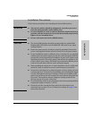
Installation Procedures
Installing the Switch
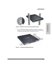
4. Mount the Switch
After the switch passes self test, it is ready to be mounted in a stable location.
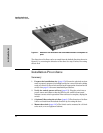
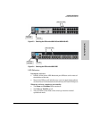
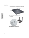
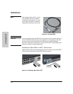
Rack or Cabinet Mounting
The Series 6600 Switches are designed to be mounted in any EIA-standard 19-
inch telco rack or communication equipment cabinet using the balanced or
center mounting orientation, see figure 2-5. Flush mounting in a two post rack
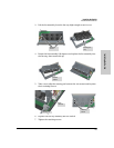
is not supported. Or with the optional Rail Mounting Kit (5070-6532) in an HP
10000 (HP 10K) rack or any 4 post racking solution, see figures 2-6 through
2-10. Secure the rack in accordance with the manufacture’s safety guidelines.
WARNING For safe operation, please read the mounting precautions on page 2-3,
before mounting a switch.
Equipment
Cabinet
Note
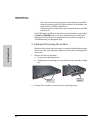
The 12-24 screws supplied with the switch are the correct threading for
standard EIA/TIA open 19-inch racks. If you are installing the switch in an
equipment cabinet such as a server cabinet, use the clips and screws that came
with the cabinet in place of the 12-24 screws that are supplied with the switch.
Complete step 1, and plan which four holes you will be using in the cabinet
and install all four clips. Then proceed to step 2.
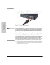
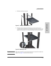
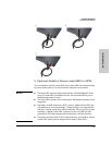
Note The mounting brackets have multiple mounting holes and can be rotated
allowing for a wide variety of mounting options. These include mounting it in
a more balanced position (which is the ProCurve recommended option for the
Series 6600 Switches when mounting in a two post rack) as shown in Figure
2-5, or mounting the switch so its front face is flush with the face of the rack,
as shown in Figure 2-6. This installation is used for mounting in a four post
HP 10K rack, see Figure 2-9.