


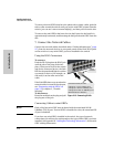


2-18
Installing the Switch
Installation Procedures
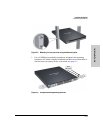
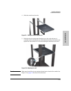
Installing the Switch
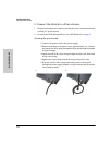
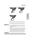
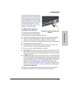
To remove the mini-GBICs that have the plastic tab or plastic collar, push the
tab or collar toward the switch until you see the mini-GBIC release from the
switch (you can see it move outward slightly), and then pull it from the slot.
To remove the mini-GBICs that have the wire bail, lower the bail until it is
approximately horizontal, and then using the bail, pull the mini-GBIC from the
slot.
7. Connect the Network Cables
Connect the network cables, described under “Cabling Infrastructure” (page
2-5), from the network devices or your patch panels to the fixed RJ-45 ports
on the switch or to any mini-GBICs you have installed in the switch.
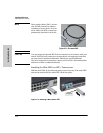
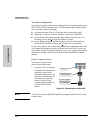
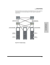
Using the RJ-45 Connectors
To connect:
Push the RJ-45 plug into the RJ-45 jack
until the tab on the plug clicks into
place. When power is on for the switch
and for the connected device, the Link
LED for the port should light to confirm
a powered-on device (for example, an
end node) is at the other end of the
cable.
If the Link LED does not go on when the
network cable is connected to the port,
see “Diagnosing with the LEDs” on
page 5-4, in chapter 5, “Trouble-
shooting”.
To disconnect:
Press the small tab on the plug and pull
the plug out of the jack.
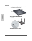
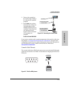
Connecting Cables to mini-GBICs
Note Each of the four mini-GBIC slots is shared with the associated 10/100/
1000Base-T RJ-45 port. If a mini-GBIC is installed in a slot, the associated RJ-
45 port is disabled.
If you have any mini-GBICs installed in the switch, the type of network
connections you will need to use depends on the type of mini-GBICs you have
installed. See Appendix B, “Cabling and Technology Information”, for the mini-
GBIC cabling information.
Unshielded twisted-pair cable:
• Category 3, 4, or 5 for 10 Mbps ports
• Category 5 or better for 100 Mbps ports
• Category 5e or better for 1000 Mbps ports
Maximum distance: 100 meters
RJ-45
connector
Figure 2-13. Connecting RJ-45s