


109
6 Tests and Error Messages
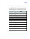
MaxiLife Test Sequence and Error Messages
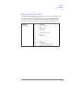
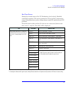
The following table shows the test sequence carried out, the type of error
message, and the action to take.
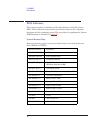
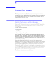
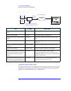
Post Test Sequence and Post Error
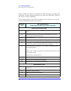
In this phase, MaxiLife waits for any error messages that the BIOS may
issue. If such an error occurs, then a screen similar to the following example
is displayed. The error code that appears on the LCD status panel is the
same as the one that appears on the monitor screen. If the POST issues
several error codes, only the last one is visible on the LCD status panel.
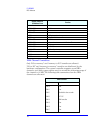
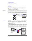
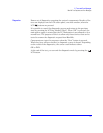
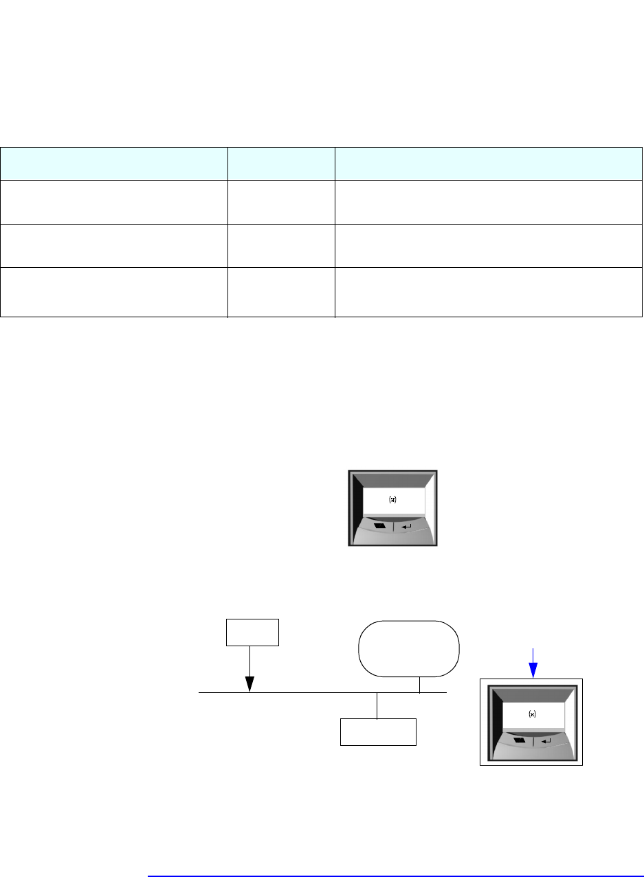
The following diagrams show the different BIOS-generated errors.
Test Error Code Action to Take
Presence of either a processor or processor
terminator
CPU SOCKET Check that the processor(s), processor terminator and VRM are
correctly installed.
Control of some voltages: VRMs, 12V, 3.3V,
1.8V, 2.5V
POWER SUPPLY Check the power supply cable and connectors, VRM and processor.
Check the system board clock generators (PLL). BOARD PLL 1 Check that the system board is connected
2 Replace the system board (PLL clock generator).
POST XXXX
ERROR
BIOS
LCD Status Panel
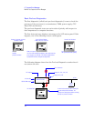
System Memory
There is a time-out of 3 seconds before
the message is displayed on the LCD
status panel and video display.
“read system memory”
MaxiLife
“Spy System
Memory”
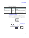
“BIOS” ERROR
BIOS
ERROR