


69
2 System Board
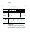
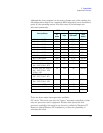
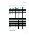
Assigned Device Interrupts
Although the Setup program can be used to change some of the settings, the
following address map is not completely BIOS dependent, but is determined
partly by the operating system. Note that some of the interrupts are
allocated dynamically.
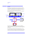
There are three major interrupt modes available:
PIC mode: This mode uses only the “Legacy” interrupt controllers, so that
only one processor can be supported. Because this system has dual
processor capability, this mode is not chosen by default by Windows NT.
However, during Windows NT installation, you have the possibility of
selecting this mode.
Interrupt Source
APIC Controller Interrupt Signalling on
of
device
Input (PIC mode)
1
1.
In PIC mode, the Interrupts signaled to the P64H are chained as INTC to the ICH.
(APIC
modes)
INTA - PCI slot 3 (64/66) P64H IRQ0 BT_INT APIC bus
INTB - PCI slot 3 (64/66) P64H IRQ1 BT_INT APIC bus
INTC - PCI slot 3 (64/66) P64H IRQ2 BT_INT APIC bus
INTD - PCI slot 3 (64/66) P64H IRQ3 BT_INT APIC bus
INTA - PCI slot 4 (64/66) P64H IRQ4 BT_INT APIC bus
INTB - PCI slot 4 (64/66) P64H IRQ5 BT_INT APIC bus
INTC - PCI slot 4 (64/66) P64H IRQ6 BT_INT APIC bus
INTD - PCI slot 4 (64/66) P64H IRQ7 BT_INT APIC bus
INTA - onboard SCSI controller P64H IRQ8 BT_INT APIC bus
AGP - INTA, PCI Slot 1 - INTC, PCI
Slot 2 - INTA, PCI Slot 5 - INTB
ICH INTA INT APIC bus
PCI Audio - INTA, AGP - INTB, PCI
Slot 1 - INTD, PCI Slot 2 - INTB,
PCI Slot 5 - INTC
ICH INTB INT APIC bus
BT_INT, PCI Slot 1 - INTA, PCI
Slot 2 - INTC, PCI Slot 5 - INTD
ICH INTC INT APIC bus
USB - INTA, PCI Slot 1 - INTB, PCI
Slot 2 - INTD, PCI Slot 5 - INTA
ICH INTD INT APIC bus
Device on Primary IDE Channel ICH IRQ14 INT APIC bus
Device on Secondary IDE Channel ICH IRQ15 INT APIC bus
Serial Interrupt from Super I/O ICH SERIRQ INT APIC bus