


PCM-9575 User’s Manual 16
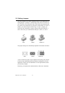
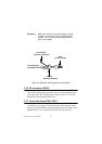
If you are connecting a 3.5” floppy drive, you may have trouble determin-
ing which pin is number one. Look for a number printed on the circuit
board indicating pin number one. In addition, the connector on the floppy
drive may have a slot. When the slot is up, pin number one should be on
the right. Check the documentation that came with the drive for more
information.
If you desire, connect the B: drive to the connectors in the middle of the
cable as described above.
In case you need to make your own cable, you can find the pin assign-
ments for the board’s connector in Appendix C.
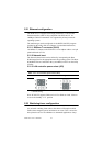
2.11 Parallel port connector (CN15)
Normally, the parallel port is used to connect the card to a printer. The
PCM-9575 includes a multi-mode (ECP/EPP/SPP) parallel port accessed
via CN15 and a 26-pin flat-cable connector. You will need an adapter
cable if you use a traditional DB-25 connector. The adapter cable has a
26-pin connector on one end, and a DB-25 connector on the other.
The parallel port is designated as LPT1, and can be disabled or changed to
LPT2 or LPT3 in the system BIOS setup.
The parallel port interrupt channel is designated to be IRQ7.
You can select ECP/EPP DMA channel via BIOS setup.
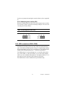
2.12 Keyboard and PS/2 mouse connector (CN25)
The PCM-9575 board provides a keyboard connector that supports both a
keyboard and a PS/2 style mouse. In most cases, especially in embedded
applications, a keyboard is not used. If the keyboard is not present, the
standard PC/AT BIOS will report an error or fail during power-on self-
test (POST) after a reset. The PCM-9575’s BIOS standard setup menu
allows you to select “All, But Keyboard” under the “Halt On” selection.
This allows no-keyboard operation in embedded system applications,
without the system halting under POST.
2.13 Power & HDD LED, Reset Button Connector
(CN13, CN22)
Next, you may want to install external switches to monitor and control the
PCM-9575. These features are optional: install them only if you need